
Mother Board And Laptop Repairing Full Course

INDEX
MOTHER BOARD
Chapter 1 :
Introduction of Mother Board ,Component of
Mother Board
Chapter 2 :
Components of circuit , ATX power supply ,
Voltage Regulator circuit of Motherboard
.
Chapter 3 :
Structure
of mosfet , Method of mosfet testing on motherboard , Numbers and types of
inductors used in motherboard , Use of power mosfet on mother board ,
Specification of mosfet Power supply on motherboard ,
introduction of power mosfet FAQs ,
place of VRM circuit of motherboard , Circuits of given signal SB of VRAM
circuit on south chipset0 , Methodes of VRAM testing , Testing of cpu supply ,
Position of testing of v-core voltage , Pentium 4 motherboard , Testing stem of
VRAM circuit of V-CORE voltage .
Chapter : 4
General circuit diagram of voltage stability
circuit for chipset , Specify of voltage circuit stabilizer for motherboard
Chipset , Design Of voltage stabilizer using amplifier IC power mosfet control
algorithm , Designing of voltage stabilizer
by using two circuit , Voltage IC , Designing of voltage stabilizer by
using Ic filters and drivers , Designing of voltage stabilizer by using
feedback voltage stabilizer IC , General question and answer about voltage
stabilizer circuit .
Chapter 5:
Ram power supply , source voltage stabilizer
circuit for video card A GP4x , 8x.
Chapter 6 :
Working
of clock generator circuit ,Special features and location of clock generator
circuit , Operation principle of clock generator circuit (clock pulse circuit ) , Methods of testing , Repairing
and mistake , Clock pulse circuit on MSI MS-6507 , Methods of fault finding and
testing of clock pulse circuit .
Chapter 7:
What
is reset signal? , Condition of IC operation , Rest signal generator on motherboard
, Rest signal generator circuit system of motherboard , Condition of south
chipset for system rest signal , Causes of rest signal losses on motherboard ,
Testing method of system rest signal .
Chapter 8:
Working of CPU , Operation testing of CPU ,
Steps of removing faults of CPU
Chapter 9:
Super I/O controller department
Chapter 10:
Bios
, Testing and fault finding of bios , bios beep code of motherboard , DG31PR ,
DH55TC , Workstation board wx58bp ,lay out of motherboard , Block diagram , Features
, penal and header detail , Beap coad , Error message and post code .
Chapter 11:
Fault finding of motherboard (color page)
CHAPTER -1
MOTHERBOARD
INTRODUCATION:
Motherboard is an electronics device which
is a printed circuit board (PCB), used in the laptop and computer. This is also
called main board or system board. Besides the computer motherboard also used
in robot and many other electronic devices. This device combines the various
components and put them at their places and also provides common power supply
to all the components. A computer is design by microprocessor, main memory and
components of motherboard and also with it , some other device and controls are
connected with motherboard for controlling the sound , video display & storage in it .
Chipset is the main part of
motherboard. Imagine of specification and capacity of motherboard is performed
with the help of chip. There are controller in the motherboard for Centre
Processing Unit (CPU) , Memory Storage , Serial Port and Keyboard and Disk
Drive . Motherboard which have minimum
one socket or one slot and have one or more microprocessor they have high
priority. And with addition they have one clock generator, one chipset, and
slot for expansion card and power supply connectors.
·
The
running speed of these device of motherboard is different.
For example: The speed
of CPU bus is 800 MHz but speed of RAM bus is 400 MHz and bus speed of sound
card is 66MHz.
·
Beside of No Bus, Street Circuit is also
different. Thus CMA devices are not connected directly with each other.
·
Motherboard is such type of device which works
at mediator for connection all the device at common linked computer in the
similar structure So motherboard performed the following function :
·
Operation
of Motherboard :
à
Mounting the components together at a computer
system .
à
Controlling the bus elements for marketing the
capable of different components.
à
Provided a clock pulse for synchronizing all
the activity of system
Due to all the important things,
because of any fault in it , computer does not work .
In the computer system, made with the
components connected on it main component of motherboard are north bridge
(north chip) , south bridge (south chip) SiO , IC(IC controller ports ) etc.
These three components of he motherboard are introduced in computer in a
unified component to perform as mediator for motherboard.
MAIN COMPONENTS MOTHERBOARD :
1. CPU Socket (for plugging the CPU) :
Here many types sockets are used for
plugging of CPU according to the category of motherboard :
·
For Pentium3 at motherboard socket 370
·
For pentium4 at motherboard socket 478
·
For Pentium D at motherboard socket 775
·
For Intel core i3 , i5 socket 1156
·
For Intel core i7 socket 1366
2. North bridge chipset (GMCH)
à
North chipset are responsible for controlling
the hgh speed components like CPU, RAM, and video card.
à
These chipset are controlling the bus speed
and they sure that between control switch And components data are continually
and smoothly obtaining or not , who are take out the speed of CPU and ram in
working mode .
à
This types chipset control the request which
are going in a definitely duration from
each medium like a traffic light , while bus speed is control of direction of
intersection in constant speed for many wheecls.
3. South bridge chipset (ICH Input /Output
Controller Hub):
The working of south chip set are same
like the north chip set but south chip control the driver components like :-
Sound card , Net card , Hard drive , CD-ROM drive , USB ports and BIOS IC and
SIO etc .
4
.ROM bios (Read Only Memory – Basic in out System):-
à
ROM is read only memory ICs and BIOS is a
programs , Which are loaded in ROM by main board manufacture . There are
following functions in the BIOS program .
à
Starting
the computer and maintaining the operation of CPU .
à
Checking the Fault of RAM and Video card .
à
Managing the Chipset Drivers for North, South
Chipset , IC-SiO & ON board Video card .
à
Providing the CMOS SETUP default setting for
those machines which cannot operate the CMOS Settings.
5. SiO (super input controller):-
à
Sio controls the Serial Port like COM Port ,
PS/2 Poart and Parallel Ports devices like Printers , Scanner , Floppy
Controller
à
SiO is also superwise the other departments at
main activities for providing the signals .
à
Integrated
Power Switch Control Circuit , Rest Signal Generate system
6. Clock Generator (Clocking)- Clock
Circuit Pulse :
à
Clock pulse play important role at
motherboard. They synchronize all the operations of computer at a same time. If
this is break then clock circuit components cannot be work properly at the
motherboard .After the first operation, these are the main sources of clocking
circuit supply.
7.
VRAM (Voltage Regulator Module ):
This is power supply control circuit
control for CPU v- core, which is design from 12v/2A circuit voltage . This is
also adjusting the voltage and current level of CPU. This circuit includes the
followings components like MOSFET , PWM IC , Phase Driver IC , dr MOSFET Flter
circuit L,C etc
8.
AGP or PCI express slot:
AGP or PCI access slot, which is
control by north chip set.
9.
RAM SLOT:
To add the RAM , RAM slot are used at
motherboard . Ram slot are control by north chip set. Memory is essential part
in a computer system.
10.
PCI:
To add like card, sound card, card in
PCI extension are controlled by south chip set.
11.
IDE PORT :
For adding gateway chipset , IDE port
drive like HDD , CD_ROM and DVD are performed by using south chip set .
12.SATA
PORT (serial advance technology attachment ) :
SATA is a technique which is adds the hard disk from computer . It is replacement of
PATA .Before coming SATA, PATA was also called the IDE or ATA. SATA uses the
thin cable for connecting the hard disk from computer, which are mounted at
SATA port at motherboard. Now days SATA are mainly used in maximum computer.
13. USB PORT (universal serial bus) :
The main function of this device is
exchange of data from each other in a serial manner with high with high speed
from USB devices. USB are two types but physically one types. In USB 1.0 data
transfer speed is 1.5mbps .data transfer speed of USB 1.1 versions is maximum
12 mbps and data transfer speed in USB 2.0 versions is 480 mbps .
14. AUDIO DRIVER CHIP:
The main function of audio port
devices is converting digital signal into analog signal and providing audio
signal at audio port . These audio driver chips are used in different from .
Audio driver port are available in different from and watt like
1.1,2.1,3.1……………7.1 audio channel.
CHAPTER 2
POWER SOURCE CONTROLLER OF MOTHER
BOARD
1. Components of Circuit :
Main functions of the Sources at Motherboard Controller are the
power switch , providing voltage stability for CPU , Chipset, RAM , Video Cards and other components .
Those subject which are needed to
understand by us , they are following :
à
Voltage of ATX power supply
à
Circuit stable voltage power supplies
for CPU VRAM .
à
Matching of steedy power supply
voltage for chipset.
à
Stable voltage circuit for RAM.
2. ATX Power Voltage :
There are two parts in ATX power supply
–standby and main sources (main power).
à
When it is connect in 220V AC power
sources than standby work immediately and provides to south chip set and Sio IC
.(the main source does not work until the power switched is not pressed the
i.e. power source does not obtained)
When you pressed switch =>effect on start
up circuit in the south chip set =>ON.P is obtained from given chipset .
When On power command is received to SiO then ON power is given to green wire
power connector for continue making on power, when P.ON = (=0V) =. Main source
main power will work.
à
Function of main source =>
Increasing the Motherboard supply voltage , given 3.3V by orange wire 5v by red
wire , 12vby yellow wire , -5v by white wire and -12v by blue wire.
·
Black wire : Common (Ground )
·
Red wire :5.0 v
·
Purple wire 5v STB (first level)
·
Blue wire :-12v
·
Orange wire :3.3v
·
Yellow wire 12v
·
White card :-5v
·
Green wire : P.O.N.(Open source
command)
·
Grey wire is PG (power good)
Similar Voltage are received from
similar color wires of all ATX power supply.
3.VOLTAGE REGULATOR CIRCUIT OF MOTHERBOARD
à
Direct voltage supply of componrnts without voltage regulator :
Some components of motherboard are obtained direct power supply without voltage regulator through ATX power supply . These components are:
· Clock generator IC (Clock Pulse) received supply from direct source of 3.3V.
· Direct voltage of 3.3 v, 5v and 5v STB are given to south chop set.
· 3.3v and 5v STB power supply is given to Sio IC from direct sources. Supply is received to all these parts directly from ATX power supply and when we are used lower quality ATX power supply then direct source supply component , given to the motherboard can be damaged .
·
Circuit
voltage :
Some components like CPU , RAM , video
cards , and chipset generally works at low voltage so generally , extra
supplies of low voltage 1.3V to 2.5V are given , downing the power levels from Source voltage 3.3V, 5V or 12V
·
VRAM (Voltage Regulator Module ) circuit :
· VRAM is regulator circuit for CPU resources. There are functions in this circuit for changing the voltage from 12V to 1.5V. For providing power supply to CPU electronics current is increased according to CPU.
· VRAM circuit down the voltage from 12V to 1.7V at motherboard which are given to the given to the CPU .
·
Chipset
regulator circuit :
·
This is voltage regulator circuit for chipset.
Intel north and south chipset are generally uses of 1.5v and VIA chipset uses
generally 3V of voltage range.
·
RAM Regulator
circuit :
· In Pentium 3 system SDRAM 3.3V are used , which are not needed of voltage regulator .
· DDR RAM uses 2.5v voltage , DDR2 RAM uses 1.8v voltage and DDR3 RAM uses 1.5v voltage . So obtaining proper voltage for these & for decreasing the voltage, we are needed the voltage regulator circuit .
à
Circuit
Description of power supply of motherboard :
· When the plug is in then reaction are start at power sources and motherboard obtained STANDBY => 5V power supply from purple wire.
· When you press the switch and controlling the sources all the circuit are in working mode like P.O.N = 0v for boot , 3.3v, 5v and 12v and a secondary sources of motherboard providing -5v and -12v and for operating main sources .
· 3.3v power supply directly given to the clock generator IC , south chipset , Bios and Sio IC And less power supply from this are provided through regulator circuit to 1.5v chipset (Intel) 3v or chipset VIA .
· Obtain 1.5 v supply voltage source from 12v through VRAM circuit , given to the CPU .
· Given power supply of 5v for chipset and PCI extension card are feed for RAM power through supply voltage regulator circuit.
à Description of process control circuit :
· When the plug is in then the voltage supply is obtained to STANDBY operation , south bridge and SIO IC before the circuit for the 5V STB .
· When you press the switch from south chipset then open sources P.ON command is obtained.
This command is given to IC. And after this controlling the main source main power activities and for power supply at motherboard P.ON is given from Sio IC .
· Operating voltage output of main sources are following :
3.3v supply directly feed to south chip set and accept for PCI extension.
For down the voltage for 1.5v power supply 12v supply is given to the VRAM voltage regulator circuit for CPU .
· If this is operate properly then this is send the VRAM _GD signal to the south chip set that V-CORE is correctly obtaining to CPU . This is signal protection circuit . When this signal is chip set CPU understand the this signal into from of ready chip set activities and provide the rest signal .
CHAPTER -3
DETAIL OF MOTHERBOARD MOSFET
Generally we see the MOSFET on the
motherboard, which is used very much. They are used in power supply control
circuit for CPU, RAM and chipset .
STRUCTURE OF MOSFET :
MOSFET (metal oxide semiconductor field
effect transistor)
MOSFET are two types and have three
pins which are as follow:
·
Base pin (drain)-D
·
Source pin (source) –S
·
Gate pin –(gate)-g
Top View of Mosfet
à
Identification
of N-Channel , P-Channel MOSFET Digital Multimeter :
·
First of all , put the multimeter in
2k or diode range .
·
Putting the red Probe at Drain & Black
Probe at Source , multimeter is showing 240 Ω to 960 Ω resistance then
this MOSFET is P-Channel MOSFET
·
Putting the Black Probe at Drain , Red Probe
at Source ,Multimeter is showing 240 Ω to 960 Ω resistance then this MOSFET is
N-Channel MOSFET .
à
.Testing of MOSFET
·
If GATE to Drain ,GATE to Source
,multimeter is not showing continuity then this MOSFET is OK and if continuity
is showing then this MOSFET is short .
·
If the multimeter is showing the
continuity both side drain to source and source to drain , then MOSFET is short
.
·
If the multimeter is not showing the
continuity both side drain to source and source to drain , than MOSFET is open
.
·
If the multimeter is showing the
continuity in one side drain to source ,source to drain and other side countinuty
is not showing then this MOSFET is ok .
NOTE: Before testing of MOSFET , making
short the drain , source and gate and discharge them.
Difference between the transistor and
mosfets :
|
MOSFET |
TRANSISTOR |
|
1. Gate operating voltage of mosfets
is 1.3V. |
1.Base operating voltage of
transistor is .3v |
|
2.Operating ng temperature of mosfets is -55 to 120 degree Celsius |
2.Operating temperature of
transistor 0 to 34 degree Celsius . |
|
3.IC made by mosfets is called CMOS. |
3.IC made by transistor is called
TTL IC. |
|
4.Positive supply of CMOS is called
VDD . |
4.Positive supply of TTL IC is
called VCC. |
|
5. Negative supply of CMOS IC is
called VCC. |
5. Negative supply of TTL IC is
called GND. |
à
Reverse characteristics MOSFETS (which are used in motherboard) :
·
Source pin is insulated from gate pin
.
·
Gate pin is insulated from drain pin .
·
Drain pin from sources pin (when D
level is positive) , voltage depend on gate pin .
·
When voltage increased from gate to
source pin (when drain is positive and
source is negative ) then mosfets becomes ON.
·
When Gate pin voltage are equal or
less than Source voltage then MOSFET becomes off. => In this condition
MOSFETS is ok
1. METHOD OF MOSFET TESTING ON MOTHERBOARD :
à
Measure
the quality control of power MOSFET :
·
For testing of quality control you have to
need to remove the gate (G) and source (S) pin from circuit then we test the
following :
Condition
of Broken MOSFET are following :
·
Measure between G&S ,then will be lower
resistance =>power detectors or shorts
-GS
·
Measure between G&D there will be low
impedance => power detectors or shorts –GD
·
After loading the positive for G (for
power)which reverse power is checked , they not lead =>
2. PW TYPE
|
PW021-**MS |
L0(µH) |
Rdc(mΩ) |
Ratedcurrent (A) |
Saturationcurrent (A) |
|
R50 |
0.5 |
85 100 |
1.50 |
2.40 |
|
1R0 |
1.0 |
120 150 |
1.20 |
1.80 |
|
2R2 |
2.2 |
300 350 |
0.85 |
1.20 |
|
3R3 |
3.3 |
430 500 |
0.75 |
0.98 |
|
4R7 |
4.7 |
600 700 |
0.65 |
0.80 |
|
6R8 |
6.8 |
780 900 |
0.55 |
0.73 |
|
100 |
10.0 |
1200 1400 |
0.45 |
0.61 |
|
P W25201B T***MS |
L0(µH) |
Rdc(mΩ) |
Ratedcurrent (A) |
Saturationcurrent (A) |
|
R47 |
0.47 |
47 56 |
2.20 |
3.70 |
|
1R0 |
1.0 |
73 88 |
1.80 |
2.70 |
|
1R5 |
1.5 |
105 126 |
1.50 |
2.10 |
|
2R2 |
2.2 |
129 155 |
1.30 |
1.70 |
|
3R3 |
3.3 |
227 272 |
1.00 |
1.30 |
|
4R7 |
4.7 |
338 406 |
0.80 |
1.15 |
|
PCMC042T_***MN |
L0(µH) inductance |
PCMC (B) type |
Ratedcurrent
(A) |
Saturationcurrent (A) |
|
|
R10 |
0.10 |
4.5 5.0 |
11 |
30 |
|
|
R22 |
0.22 |
7.3 8.0 |
9 |
17 |
|
|
R47 |
0.47 |
14.0 15.5 |
6 |
11.5 |
|
|
1R0 |
1.00 |
32.0 36.0 |
3.8 |
8.5 |
|
PCMB042T_***MS |
L0(µH) inductance |
Rdc(mΩ) |
Ratedcurrent
(A) |
Saturationcurrent (A) |
|
R10 |
0.10 |
3.5 4.0 |
12 |
22 |
|
R22 |
0.22 |
6.0 6.6 |
9 |
13 |
|
R47 |
0.47 |
12.5 12.0 |
7 |
9.5 |
|
1R0 |
1.00 |
24.0 27.0 |
4.5 |
7.0 |
|
1R5 |
1.50 |
38.0 46.0 |
4.0 |
6.0 |
|
2R2 |
2.20 |
58.0 58.0 |
3.0 |
5.0 |
|
PCMC053T-***MN |
L0(µH) inductance |
Rdc(mΩ) |
Ratedcurrent (A) |
Saturationcurrent (A) |
|
R68 |
0.68 |
11.0 12.0 |
8.5 |
14.0 |
|
1R0 |
1.0 |
13.0 14.0 |
7.0 |
11.0 |
|
1R2 |
1.2 |
15.0 16.0 |
6.5 |
11.0 |
|
1R5 |
1.5 |
18.0 20.0
|
6.0 |
10.0 |
|
2R2 |
2.2 |
29.0 35.0 |
5.5 |
9.0 |
|
3R3 |
3.3 |
32.0 38.0 |
5.0 |
7.0 |
|
PS031T-***MS |
L0(µH) inductance |
Rdc(mΩ) |
Ratedcurrent (A) |
Saturationcurrent (A) |
|
2R2 |
2.2 |
75 90 |
1.40 |
1.10 |
|
4R7 |
4.7 |
120 140 |
1.20 |
0.77 |
|
6R8 |
6.8 |
160
190 |
1.00 |
0.67 |
|
100 |
10.0 |
260 340 |
0.90 |
0.54 |
|
PS031T_***MS |
L0(µH) inductance |
Rdc(mΩ) |
Ratedcurrent (A) |
Saturationcurrent (A) |
|
2R2 |
2.2 |
90 105 |
1.30 |
1.10 |
|
3R3 |
3.3 |
130 150 |
1.20 |
0.90 |
|
4R7 |
4.7 |
170 200 |
1.00 |
0.75 |
|
6R8 |
6.8 |
200 230 |
0.90 |
0.65 |
|
100 |
10.0 |
300 340 |
0.80 |
0.52 |
|
PS014B_***MS |
L0(µH) inductance |
Rdc(mΩ) |
Ratedcurrent (A) |
Saturationcurrent (A) |
|
2R2 |
2.2 |
80 95 |
1.30 |
1.70 |
|
3R3 |
3.3 |
100 120 |
1.10 |
1.40 |
|
4R7 |
4.7 |
120 145 |
1.00 |
1.15 |
|
6R8 |
6.8 |
180 216 |
0.84 |
1.00 |
NOTE : when we check the quality of power
MOSFET for correction result then for this remove the G&S pins from the
printed circuit .
3.USE OF POWER MOSFET ON MOTHERBOARD
:-
1. In the voltage Regulator Circuit MOSFET is used for amplified
the electronic current .
2. Function of MOSFET in RAM voltage
circuit is amplified the electronic . IC LMV algorithm Control the gate of
MOSFET by amplifies voltage control . From which voltage regulator circuit
provide a constant current and this circuit is provide the effective voltage .
MOSFET is connected to voltage through
the coil . DC pulse from is changed into
pulse width input voltage is converted into output as we wise and we can down
this voltage
When the high logic is obtained at the gate pin then at drain pin of
MOSFET Logic low value (Logic Value 0 ) is obtained .
3.SPECIFICATION OF MOSFET SUPPLY ON
MOTHERBOARD :
·
The specification of motherboard is
that voltage is low and current is high .
Example of line voltage :
12v , current dissipation is approximate 2 to
3A.
5v, current dissipation is approximate 1A .
3.3v, current dissipation is
approximate 4A.
CPU uses between 1.5v but
current dissipation is approximate 10A.
=>thus power MOSFET of motherboard
uses low voltage but need much current dissipation . For replacing this monitor
power MOSFET cannot be used which are
established at motherboard .
Example 1: Information of number of power
MOSFET at motherboard .
-
Voltage tolerance is only 30v is
between the D-S.
-
Till 42A connection is obtained
through the D-S.
Example 2: Power MOSFET IRF-630 which uses generally pressures vessels of
monitor . Which have following
parameters : voltage 200v which is given to DC but only 9A current in
line ?Power Impedance DS is low 4 ohm compare to 0 ohm .
3.INFORMATION ABOUT POWER MOSFET :
6.FAQs:
Q1: For what purpose power mosfets on
motherboards are generally used ?
Ans. Following circuits are used in the Power mosfets on motherboards.
Voltage regulator circuit , voltage regulator circuit for CPU (VRAM circuit ) ,
power voltage regulator circuit for chipset, voltage regulator circuit for RAM
, voltage regulator circuit for video cards.
Q2. Power mosfet on motherboard are
damaged because they work in description and crupts power line, when the
voltage components are beings short supply by mosfets ?
Ans : When the RAM or RAM’s pin are short the vcc , then power MOSFET
,connected for RAM voltage are short or
burst .
Q3. What should do when the power MOSFET on board burn of damaged
?
Ans. If there can be shorted in the power
MOSFET VRAM circuit or RAM voltage regulator then ATX power fan will become off
after moving one or two times
-
In this condition when supply power
MOSFET of RAM becomes or burn , then long beep is received to the RAM for
switch OFF , which will be the cause of VVC power fail .
-
When the top MOSFETS of RAM becomes
shorts then RAM voltage are increased and RAM continue damaged
-
1.PLACE OF VRAM CIRUIT ON MOTHERBOARD
à
What is VRAM ? VRAM (Voltage Regulator
Module ) is Stable voltage circuit for CPU.
-VRAM circuit (Voltage Stability for CPU )
generally placed in-front of CPU socket . There are following components in
this circuit :-
-PWM IC(VRAM chip )
-Phase Driver IC
-Power MOSFET
-Coli
-Filter capacitor
Function of VRAM circuit provides a constant
according to current of CPU for CPU power supply .
2. LOGIC CIRCUIT DIAGRAM OFVRAM MOTHERBOARD:
à
Main components of VRAM circuit :
-PWM IC (Pluse PWM –Pulse Width Modulation ) :- Oscillator works for controlling the Pairs work of power MOSFET .
-Face driver IC : It is divide the opposite two range
-Power MOSFET : Its activity is done according
to PWM pulse control signal , when positive pulse of pulse is received then MOSFET becomes ON and when
negative pulse of phase is received then MOSFET becomes OFF.
-Coli : For filtering the DC voltage pulse in the DC voltage , It is
connected with the Capacitors.
-Capacitors : For filtering the DC voltage pulses in the DC voltage
, It is connected with the coli.
à
Working principal of VRAM circuit :
-When supply is received at P Good (Pin Press
ATX Power Problems) without any Up /Down in the VCC voltage then PWM IC will
generate, It is generate three pairs of PWM1, PWM2 & PWM3 for MOSFET .
-When this PWM pulse passes from phase drive
IC then divided into two pulses with opposite phase that time opposite control
pulses are given to the gate of phase -2 powers MOSFET.
-When power pulse is positive then MOSFET
drivers becomes ON. it has power control pulses which are break and oscillator
frequency of PWM pulses continue shut down the power MOSFET .
-In each phase one pairs MOSFET is used , by which
alternate phase is received , according to the received phase , one voltage
pulse is generate in between the MOSFET .
-Through voltage pulse filter circuit
à
Specification of VRAM circuit :
-This is converting the 12v into 1.5v and low current to high
current . it obtain the 16 phase voltage convertor circuit from the phase 2.
- Very low losses of capacity in then self
circuit . which is approximate only 20% of effectively capacity .
- In VRAM , there is ability the CPU voltage
level signal in the automatic shape according to logic at VID1, VID2 ,VID3 and
VID4 pins according to the report received from CPU.
- CPU does not add the value of VID pins 1 on
Pentium 4 motherboard and by defaults logics circuit provide the 0v VRAM
voltage .
-There are 4pin connector for 12v Input to the
VRAM circuit of motherboard
Details of PWM pinsLoscillation IC) :
-VCC –power supply for IC .
-PWM1 , PWM2, PWM3: This is pulse width modulation for
controlling the lead pair of power mosfets .
-ISEN1,
ISEN2,ISEN3 : Pins of current sensor
-EN_IC-pin for operations .
-ENLL(PGOOD pin ): ATX power station operates correctly.
-VID0,VID1, VID2 , VID3, VID4 pin : status logic voltage value for uses of CPU .
- PGOOD
,OVP : VRAM circuit status of south chipset .
-VSEN –voltage sensor (feedback pins )
3.
VRAM CIRCUIT OF MSI MOTHERBOARD :-
4.
SIGNALS CIRCUIT, GIVEN TO
THE VRAM CIRCUIT AT SOUTH CHIPSET
-When the VRAM circuit is correct for CPU and CPU is ready for
working ,then signals are out from the VRAM circuit for south chipset then VRAM
is working properly which is known as VRAM_GD (VRAM GOOD).
-This VRAM_GD signal is used as a condition for reset the south
chipset system . If VRAM circuit does not working properly or there is same
problems in it then VRAM_GD signal dos not obtain to south chipset and thus
signal is not reset for boot .
5. TESTING METHODS OF VRAM CIRCUIT –
(TESTING FOR CPU SUPPLY ):
When the voltage level is test for CPU then the following points
to be noted given below :
-CPU vCore voltage can be check without connection the CPU at CPU
socket in the Pentium3 motherboard
-For testing of CPU supply we need to plug CPU in CPU socket in Pentium4 motherboard , after this you can
check the voltage. if there is no CPU in
VRAM circuit in main pen 4 then the voltage is by default is 0v .
-We need to test v core voltage before connecting the CPU socket
for testing the CPU voltage and prevent from the shorts of VRM circuit mosfets
because the increased voltage can damaged the CPU .
6.POSITION OF TESTING THE V-CORE
VOLTAGE
-
Please measure the v-core voltage (voltage for
CPU) which is test between the starting by the DC Coli , you can be measure on
coils , if the supply voltage id
approximate 1.5v DC then circuit is
correct but if the supply voltage is 0v or less than 1v than VRAM DC is
damaged .
For testing of CPU voltage level tests the positive on the top of
the capacitor or inductor .
When measure the supply voltage sockets must be placed between the
main boards Pentium 4 CPU for CPU and output voltage must be measure the
starting (inductor must be common from 2 to 4 in output size.)
7. TESTING STE3PS OF VRAM CIRCUIT OF
PENTIUM 4 MOTHERBOARD V-CORE :
Steps1: Measure the v-core voltage
for 0v when the CPU is not attached , If this is not install already , when the
v-core voltage CPU VRAM has been shorted then the greater then 12v voltage is
obtain on the mosfets .
Steps2 : Install the CPU , switch ON the power supply and measure the
v-core voltage on pin of coil.
-If the voltage between the 1.5v than circuit is correct .
-If there is no voltage or less than 1v, output voltage is low
than VRAM circuit is damaged .
à
Follow these steps and check after this follow steps:
Step1: (On the source and measure the voltage without CPU )
-Supply the power to the motherboard , supply
the 12v regulation for on the v-core voltage ,and measure voltage on the top of
the top of the inductor circuit of VRAM voltage stabilizer .
-Use the test card for checking the status of
power source
-On the main switch for running the main
switch (PWR pin shorts) . if the 3.3v,5v, and 12v lamp is on on the ATX light of test card than card i.e.
main board is not shorts .
-Measure the 0v on pin of inductor . (CPU VRAM
output voltage circuit defaults =due to 0v).
à
=>If the CPU voltage is not
obtaining and 5v to 10v voltage
are obtaining the top of the inductor than the mosfets circuit is shorts . Test the mosfets with carefully.
à
STEP2 : (on the power source and measure the volt on
CPU in socket , which are established on the main board.).
-Install the CPU in socket on the motherboard .
(be sure that CPU correct .)
-Power the motherboard ; supply the standard
10v DC v-core voltage to voltage regulation
Measure the voltage on the top of inductor
circuit of the VRAM voltage stabilizer .
-
Use the main test card for testing of
status of power sources .
-
- On the main switch for running the
main switch (PWR shorts legs ) . And measure the 3.3v, the 1.5v on VRM circuit
ofr the CPU voltage .
-
If that measure we obtain the 0v (V
core voltage 0 than VRAM circuit is not active .
à
You need the following methods for correcting the circuit :
- Dry the vacuum
oscillation pulse PWM IC and PHASE .
-
Check that there is any shorting in the MOSFET .
-
Change the PWM Pulse oscillation IC.
CHAPTER
-4
CHIPSET POWER SUPPLY
-
North
chipset uses the 4VCC , in which two for south chipset and two common voltage
for CPU ,RAM
-
5 lines
south chipset voltage are used with 1.5V and 1.8V south chipset voltage . Among
these three Voltage STB5 , 5V and 3.3V
are directly received from the ATX source.
2.IDENTIFICATION OF VOLTAGE STABLIZER CIRCUIT
FOR MOTHERBOARD CHIPSET :
The selection of right voltage
stabilizer circuit for motherboard
chipset becomes complex due to following reasons –
-
Chipset in
pins cannot be measure by using the any pin clearance .
-
- There are
Printed Insulated Circuit backside of the chipset is painted by the paint .
-
-In the life
time of many motherboards uses the many voltage stabilizer circuit .
-
Many
different voltages are used in different types of chipset.
à
YOU can identify based on the following
characteristics specification :
-For two chipsets voltage
stabilizer circuit generally placed area between the both chipset .
-When they work than supply pin
at 1.5v and 1.8 v .
- 8pin IC used for control the
MOSFET circuit .
- Some new motherboard are used
at the [power source of CPU . So these are the coils circuits. .
Measure the supply pleased
between the chipset of power mosfets which is 1.5v or 1.8v , which is power
voltage stabilizer for chipset .
3. VOLTAGE ST^ABLIZE CIRCUIT DESIGN BY THE
OSCILLATION DRIVER SIGNAL POWER IC MOSFETS :
- Output voltage can be changed by changing
the value of resistance by using the feedback circuit which is imposed on the
need of distributions .
·
Operation principle of circuit :
When supply is given in it then
the voltage stabilizer IC , generate the control voltage for G pin of MOSFETS .
This generated voltage obtain on gate
pin of MOSFET than MOSFETS provide the 1.5v voltage for supply load, this is
for supply chipset , In the electrical circuit , Voltage received at source pin
of power MOSFETS are given to the feedback pin of IC for controlling through
the resistance R106 and R107 . If there is increasing in the output voltage of
any reason then the value of voltage at feedback pin in increases . So the IC
will provide the control signal as automatic for decreasing the voltage ,by
which output voltage are decreased . When output voltage are decrease then
control process works its opposite .
In this circuit , there are
adjustable voltage from 1 V to 3 V , when we change the value of resistance
R106 , R107 for distributing application , which is changing the feedback
voltage of FB pin of the IC .
2.Voltage Stabilizer Circuit Designing by
using the Amplifier IC Power MOSFETS Control Algorithm:
Used in the Voltage Stabilizer
circuit for Chipset and RAM Power Source .
·
Description of Circuits :
-
- Zener diodes which are connected to pin no
.10 of IC generate the voltage of opposite standard .
-
Pin no. 4 is
VCC source pin
-
Pin no . 8
of IC is used for ON the DC voltage power MOSFETS .
·
Principle of voltage :
-
- Voltage are fixed of Pin no .10 of IC by
using the Zener diodes , reduction voltage are obtain at th pin no .9 , then
voltage are obtain at the pin no . 8 of
IC .So the output voltage of power mosfets is low .
*Suppose there is increasing in
the load current consumption then output voltage are decreasing . After this ,
feedback voltage will decrease at pin no . 9 and the principal of algorithm ,
result will be be received in the increasing flow for increasing in the power
load .
Voltage stabilizer circuits by connecting two
circuit:
-
For
increasing the quality of output voltage, the circuit can be design by
connecting the two circuit . As shown in the circuit .With this type of circuit
, one power voltage will decrease the voltage through the DS of stabilizer circuit , by which it decrease the
power , which should be feel by it .
If we want to change the output voltage than
we can change the value of resistance R173and R174.
5.
Voltage Stabilizer Circuit design by using
the voltage IC , LC filters and drivers
:
-
This is
principal circuit of voltage stabilizer circuit , which is operating similar to
VRAM circuit (voltage stability circuit
for CPU ) . This circuit generally used in high quality motherboard circuit .
from this motherboards obtain the more life .
-
IC-RT9214
used in circuit is 8 pin IC. ( As shown below in fig with operation principal)
|
Pin no. |
Name of
pin |
description |
|
1. |
BOOT |
This is supply pin for upper gate
drive department , |
|
2. |
UGATE |
This is upper gate driver output
pin of IC , which is connected to gate of high site power |
|
3. |
GND |
This is the ground pin of IC . |
|
4. |
LGATE |
This is lower gate driver output
pin of IC , which is connected to gate of low site power mosfets . |
|
5. |
VCC |
This is positive supply pin of IC
, which is operate at 5V to 12V . |
Voltage stabilizer circuit design by the
feedback voltage stabilizer IC
-
It is
similar to power MOSFET IC and driver IC , which is capable of feedback
pressure LM-1117
-
The
principal operation of this IC is very simple . The circuit diagram of this IC
is given below ; you are making the constant voltage .
-
In the
output voltage , as you want for
changing like the same , you can generally change the value of R2.
But line is not increased , this
circuit only secondary voltage like 1.8v voltage for chipset used only for
control .
·
General question and answer about the chipset
voltage stabilizer circuit :
Q.1What will be happen if the voltage
stabilizer circuit of motherboard is break ?
Ans :- if
voltage stabilizer does not working for for the chipset (i.e . . chipset not
getting the 1.5v or 1.8 v supply, then chipset will not work , by which
motherboard will not boot , no information will be obtain by the beep on the
screen , but at this time pop open source also working from which fan is moving
.(Due to 5v STB supply by the open circuit voltage ).
-When you
check this you will see that the main card test test RST lamp is continue on or
off. (it is the result of when all the carefully are loosed ).
-If the is
mosfes being shorted =>Then this provided the 3.3v or 5v both voltage
,chipset which is warm and damaged after some the operating .
Q.2 How you will decided that who are the
power mosfets voltage stabilizer of chipset power
Ans :-Pin
of chipset , which gives the power to the chipset . They are elevated so this
can not be measure . But this can be done based on various features .
-
Voltage
stabilizer circuit generally placed between the areas of two IC for the chipset
.
-
3.3v voltage
is obtained at pin D of power mosfets .
-
1.5v (with
Intel ) DC or 3VDC (for VIA chipset ) voltage are obtained at pin S of power
mosfets of voltage stabilizer circuits.
Q3. What is the reson of damaged thj=e south
chipset?
Ans:- The
reason of damaged the south chipset is as following :
-Chipset –due
to short of 5v, 3.3v or line source.
-When system
is not reset from our signal .
·
Details of shorts chipset are as follow:
If the chipsets is warming ,
before the power switch becomes ON or after the ON –Chipset is vary hot
(heating produces by toching the hand )
=> This is describing that south chipset is
shorts and At this time you need to change the suth chipset .
When the good chipsets work than the heats of
this chipset is 40*C.
*signal
does reset the south chipsets .
- When the south chipset does not emit the
reset signal than motherboard is dead .Loss of reset signal is done by the test
card . . When the reset signal is not obtain than north chipset does not work
and also other components does not work . Mother is not boot and display will
not be obtained.
Reset signal
system can be tested by the test card main . If the reset signal is lost at the main than the system chipset
north , CPU and other components can not
work . So the motherboard will not boot ,information will not reached
there that what are happening or neither
screen will be obtained .
After some
time to operates system will display the reset signal (PCI RST #).
Damaging of
reset (Like –No Light or Bright Light Reset but No Short) produces due to the
followings of south chipset , for example :
-
Not
obtaining the 1.5v or 1.5v power supply for the chipset (Broken Circuit
Stabilizer )
-
ATX power
failure for mail chipsets , from which PG voltage are loss (signal sources
incident ATX ).
-
Problem in
VRAM circuit (CPU voltage ) or CPU signal is not obtaining the VRAM-GD south
chipset
-
Pines of
south chipset are broken or dry sold .
Reason of damaging the chipsets:
-Direct use of chipset voltage
STB5v, 5v,3.3v, when we use the low quality ATX this is directly affect the
chipsets or failing of ATX power. Thus the reason of failing of south chipsets
is mainly ATX source .
-South chipset driver components
like extension card on PCI slots drive on the IDE slots , USB ports . So if the
sounds cards or devices , like hard disk drive failure with the line the signal
sources from shorting than the south chipset
is damaged .
CHAPTER -5
POWER SUPPLY OF RAM
1.Voltage for RAM
|
RAM Type |
Used Voltage |
Even |
Voltage Stabilizer Circuit |
|
SDRM |
3.3V |
168 |
not |
|
DDR |
2.5V |
184 |
have |
|
DDR2 |
1.8V |
240 |
have |
|
DDR3 |
1.5V |
240 |
have |
2- SDRM work at
3.3V , these voltage are available already on the motherboard , SDRM does not
required the voltage stabilizer circuits .
-
DDR, DDR2
and DDR3 RAM need the voltage below the 3.3Vand 5V so this voltage need to down the voltage by using the voltage
stabilizer circuit this iow voltage is given by according to need .
3.LEG OF DDR
VOLTAGE SLOTS :
Power supply pins of DDR slots – voltage 2.5V
-DDR slots are 184 pins , required voltage
level is 2.5V for DDR slots and pins of power sources for DDR slots are shown
above , which have many member of pins.
(7,15,22,30,38,46,54,62,70,77,85,96,104,108,112,120,128,136,143,148,156,164,168,172,180,184
including these pins )
NOTE : counting ‘s of pins is , as shown on DDR
slots RAM are divided into two zones , a long slots are on the left side and
small zone on the right sides , counting ‘s of pins are start in row wise like
1,2,3……..92 . After this we start left to right serial 93,94,95……184.
4.VOLTAGE
PINS OF DDR SLOTS :
-DDR2 slots
power supply voltage is 240 pins IC , 1.8V voltage for DDR2 (above circuit
diagram show the DDR2 slots ).
NOTE : counting’s of foot of DDR2 slots , as shown
above ,RAM is divided into two zones ,at the left side , for a long segment of
DDR2 Slots , at right side , for a shorts zone , In the first second row
counting from left to right from serial 1,2,3……to 120 , after that count left
count left to right in the row from 121,122,123…….to 240
5.Voltage leg of slots DDR3 :-
-There are 240 pins in DDR3 slots . Power
supply of DDR3 slots have the 1.5V which is shown in above of slot fig .
NOTE : Counting’s of pins , as shown at DDR3 slots
RAM is divided into the two zones the right side zone is longs and left side
zone is small zone , pin counting of slot ,from left to right serial 1,2,3….120
& counting of second row left to right , from 121,122,123…..to 240.
6.
Lcation of power source voltage stabilizer
for RAM :
-Generally , power MOSFETS and controller IC
of stable voltage circuit connected , near about RAM slot . Working procedure
of this circuit is totally the same like the circuit of chipset voltage
stabilizer .
7.RAM power
source voltage stabilizer circuit of gigabytes motherboard 3i845PE:
Power
control IC –W8833301 used for RAM and power MOSFETS components placed around the RAM slots In the I-W-83301
three port control are used .From which for 2.5V volt stabilizer circuit output port is used for
RAM.
The out drive pulse on the gate of MOSFETS Q1
are given to he pin no.20 of IC-W-83301.2.5V volt is out by the MOSFETS Q! For
DDR .
8.Method of
decides of voltage stabilizer circuits for power MOSFETS RAM :
--When we see many power MOSFETS for RAM
-For this easy method is that check the resistance
around the RAM slots of power MOSFETS’s pin S. From which MOSFETS source show
the 0 value of resistance , that is power Voltage Stabilizer for RAM.
If the 0E impedance between the RAM power pin
and the MOSFETS source pins than this is power voltage stabilizer circuit for
RAM .
If the impedance is more than 0E between he
RAM power pin and the MOSFETS source pins then that is not power voltage
stabilizer circuit for RAM.
9. General question and answer about the
voltage stabilizer circuits for RAM :
Q.1. What is show the machine when there is no
power supply for RAM ?
Ans: When there
is no power of RAM at the time of booting then the machine show the continue
long error beep and nothing will be
obtained on the screen of the computer .
Q.2. How will be
decide early that where the power supply circuit of RAM ?
Ans: For
deciding the power voltage stabilizer circuits of Ram you will check the power
pin of RAM (VDD pin ).
It will be
decide to checking the resistance by MultiMeter Resistance at source pin of
power MOSFETS connecting around the RAM Slots and between the power supply pin
of RAM slots .If the 0E resistance is obtained from any power MOSFETS then that
is power voltage stabilizer circuits for Power MOSFETS RAM .
Q.3. How
will be decided of power MOSFETS driver for RAM voltage stabilizer ?
Ans: Measure the
resistance at G and S pin of RAM power supply MOSFETS and at the IC near about
the RAM Slots .From which pin of , 0IC impedance is obtained , that is the
MOSFETS Driver IC.
For example
: Pin to pin is connected through the drive IC in the below circuit of G and S
pins
Q.4. if the RAM power is loose then machine
is boot but cannot be fast , why ?
Ans : losing
of power supply voltage machine is constant in boot condition and error beep message
is obtain from the speakers .
-
Although
some condition is that in which motherboards , computer is not boot after
checking the status of voltage stabilizer circuit for RAM .
If the voltage stabilizer
circuits make the new signal for RAM
PWR_OK which is provides the PWR_OK Resets signal to the new system of south
chipset .
RAM voltage stabilizer circuits
made by using the IC ISL6625 and two MOSFETS is signal report logic controller
at pin no . 15PG_VDDR .If there is power loss for RAM then PG_VDDR signal will
be loss ..It prevents the logic circuit and PWR_OK (good source levels) signal
will not generate by which chipsert does not generate system reset signal .
Controller Logic testing signals
are follows on some motherboards :
PWROK_VRM : Good for CPU supply voltage stabilizer
circuits
PWROK_ATX
: ATX power
source works properly .
PG_VDDR : Good for RAM voltage stabilizer circuits
PG_V1V5 : Good for chipset voltage stabilizer
circuit
Now , there are four full power
good signal at new logic controller , which is given the PGood South Chipset
generate the Reset Signal ,which is given to all.
Source Voltage Stabilizer Circuit for VIDEO
CARD APG 4X, 8X:
1- Supply
voltage AGP Video cards :
-
3.3V voltage
are given to AGP 1X ,2X video cards , so the voltage stabilizer circuits is not
needed which is use the 3.3V directly on motherboards .
-
AGP 4X and
8X video card uses the 1.5V supply voltage . So , there is need a voltage
stabilizer circuit for down the 5V supply to 1.5V or 3.3V for AGP card .
CHAPTER -6
Clock
Generator Section
1.Working of clock generator circuits
(i) Clock Generator (Clock Generator –Clock
Circuit Pulse )
- Clock
frequencies are know as computer owners .It is correcet in case of time , so
this is called the clock , which is clock time .
(ii) Meaning of clock pulses on computer :
-Clock is
very important on computer , this is move below for describe the Value of data
.If clock pulse is not move with serial data than this is meaningless .
-Digital
signal processor IC does not work without clock in some system , so clock is
compulsory for IC so that computer work correctly .
- Meaning of
clock that synchronies the data of computer
2.Location
and Characteristics of clock generator circuits
(i) Location
of clock generator circuit diagram on
theoretical diagram :
- A clock generator circuits diagram on
theoretical diagram :
-A clock
generator circuit does not depend on other components of motherboards . This is
design by theoretical diagram . This is first operation after main supply
sources and provides the different clock frequencies on different components .
(ii) Placing
of clock generator circuits on gigabytes motherboard:
Clock pulse circuit –IC circui with clock Generator 14.3MHz quartz
stand at gigabyte motherboard
(iii)
characteristics of identification of clock generator circuits on motherboard
-
Watch a IC
on motherboard which have oscillator (14.31MHz) of 2 pins and generally 2 sides
pin in this IC , from which identify the clock generator circuits .
-
-Pins of IC
clock generator circuits on ASUS motherboards are in two lines and 14.34MHz
crystal oscillators are placed near this IC
3.Operation principle of the clock generator
circuits (clock pulse circuits ):
(i) Logic circuits diagram of clock generator
circuit :
Specification of clock generator IC:
Vdd
: 3.3Vpower supply .
FS0,FS1 and FS2 : Select
pin for CPU clock frequency .
CPU STOP : Clock
signal of CPU to stop the operation .
PCI_STOP : Clock
signal of PCI to stop the operation.
PWRDN# : Signal
power off.
SDATA : Exchange data with south shipset and RAM
SCLOCK : Talking
clock .
PWE_GD# : Reporting
signal about the ATX power voltage stabilizer circuits and motherboards .
XTAL : oscillator pins .
CK_CPU : CPU
clock supply .
CK_MCH : Clock
for north chipsets.
CK_AGP : Clock for video cards .
CK_ICH :
Clock for south chipset .
CKFWH : Clock for RAMBIOS.
CK_LPC : Clock pulse Sio-IC
CK_LAN : Clock for on broad networks card
ICs.
CK_MPC : Clock for PCI slots
CK_SLOTS : Clock for PCI slots
CKM_1M : Clock for south chipsets IC,SIO
and video cards .
(ii) Operation principle of clock generator
circuits :
-When the
supply 3.3V is applied at the VDD in IC of circuits then the pulse oscillator
circuits operate and generate the 14.318 MHz standard frequency . After this ,
this circuit will generate manyn clock pulses with the help of standard quartz . After this to provide the
clock pulse on motherboards of different components they are divided into
different definite percentage .
NOTE :
VttPWR_GD#- This is obtained by collects the logic clock
circuits of signal PG.( PG power good signal infrom about the ATX).
VRAM_GD –
Information about the CPU voltage stabilizer
PG_VDDR-
Information about the voltage stabilizer circuits for RAM .
PG_V1,5V- Information
about the voltage stabilizer circuit for chipsets
If the problem is occurs on 4
departments of ATX ,VRAM circuit’ chipsets voltage stabilizer circuit ,and RAM
voltage stabilizer circuits than the signal pulse is not obtained and pulse
VttPWR_GD# does not work.
Thes circuits inform about the
pulse clock IC and control the south chipsets for voltage stabilizer circuits .
When this voltage stabilizer circuit is failed => than signal PWR_GD is not obtained =>clock
Generator and chipsets will not
work .
4.Methods of
repairing the faults and testing
(i) obtain features onmachine when the clock
pulse generator circuit is breaks :
- Before testing the clock IC ,checks the ATX
power supply (main source ), VRAM (CPU Voltage ) voltage stabilizer circuits ,
RAM voltage stabilizer circuits and chipset voltage stabilizer circuits on
motherboards .
- Clock
circuits provide a pulse for other components of motherboard . For CPU chipsets
,,north south chipsets , Sio ,ROM BIOS , AGP SLOTS PCI IDE……….
Thus, when
the clock generator circuit is break then the motherboard will not boot , fan
will be turn but source computer will not boot then the information is not
obtain neither the sound nor on screen .
(ii) Testing methods of clock pulse : -Use of main of main test cards , connect the
power supply at motherboard and Test cards on PCI slots and switch ON the power
, check the status of clock light (when you check the clock then there is no
need to connect the CPU at Pentium 3 motherboard , but there is necessary to connect CPU at
Pentium 4 motherboards .)
NOTE :
Before connecting the CPU on motherboard , you should to check the v-core
voltage of VRAM circuit for damaging the CPU from high voltage .
*(Short the
power switch plug pin with screw driver made on the front panel for making ON
the motherboard)
2.1Where the good clock pulse is obtained
from circuit test :
When Light
is Light Up (Light maintenance) at card test main CLK then following
information are provided
-
Self clock
generator which is working on the motherboard.
-
Atx Powe
supply for CPU VRAM voltage stabilizer & other circuits generally working
properly .
2.2
In the condition of clock pulse not received
then test following type , where the bright light is not received in testing by
main test card then this is done due to damage tha tracks in the clock
generator circuit .
-
Solder the IC pin .
-
-Due to
breaking of 14.31MHz oscillation .
-
Damaging of
IC clock generator circuits does not work .
2.3
When the CLK bright light is obtain for
sometime (10 seconds) and after this is off.
It is occurs due to one of them .
-ATX power fail => PG voltage
is not obtained
- VRAM circuit (CPU Voltage ) is
not working or providing wrong voltage => VRAM_GD signalis not
obtain
- Problem in voltage stabilizer
circuits for RAM (only few new pulse are obtaining ).
(iii) In this solution clock pulse is obtained
.)When the tested is performed by the
test main cards then CLK not gives the bright light ).
Reason :
It is mainly occurs due to tha
damaging of tracks in lock generator circuits
-Solder the IC pin.
-Due to breaking of 14.31MHz
oscillation .
-Damaging of IC clock pulse is
not obtained .
Repairing :
-
Identify the
location of clock generator circuits .(See the IC on motherboards in which pins
in two sides and 14.318 MHz oscillator are placed , that is clock pulse IC and
pulse clock generator circuits ).
-
-Clear the
area around the IC .
-
Use the hot
air gum for removing outside the pulse clock IC .
-
Similarly do
for 14.318MHz oscillator.
-
Before changing the clock pulse IC ,it is
essential to test with test card again after each work .If the clock light is obtaining
than the clock is obtaining .
(iv) In this solution clock pulse is obtained
.(when we use the main test cards than the CLK gives the bright light for some
time and after this it is off .)
Reason:
This is occurs due to following reason :
-Losses of ATX power by which
clock pilse is not obtained .
-Losses of VRAM circuit voltage
problem due to VRAM_GD or you are not connecting the motherboard CPU.
-14.318MHz are not obtaining at
Quartz oscillation circuits .
-Dry sold of clock IC.
Repairing :
-Check the ATX power .
-Placed the CPU in Motherboard
and check this .
-Check the circuits’ voltage and
check the VRAM voltage for CPU core .
-Change the 14.318MHz oscillator
.
- Dry vacuum the pulse clock IC.
i. Clock pulse for PCISOLTS .
2.Faults and repairing methods of clock pulse
circuits:
(i) Description : on the
computer power switches . Fans move power source , machine is not boot , sound
is not obtained the speakers and nothing is obtained on the screen .
Reason : This
fault occurs due to following reason :
-
Faults in
clock generator circuits=> clock pulse are not obtained for components at
motherboards .
-
-Power
supply not obtaining due to faults in VRAM circuits .
-
Faults in
chipsets power supply
-
Due to
faults in south chipset system is not making the resets signals.
-
CPU pins are
not properly connecting to the CPU sockets.
-
ROM IC is
damaged or BIOS program crupts
Checking by serially :
In this fault we first check the
clock pulse .For removing the problem of the clock pulse we use the new clock
IC.
Methods of testing :
-
For testing
do not place CPU and ROM on the motherboards .
-
Fro supply
he motherboards connect the motherboard from 20 wires and 4 wires .
-
Mount the
motherboard test card on PCI slots .
-
Shorts the
PW main switch by using the screw driver .
-
Check the
CLK light on motherboard test cards .
ð
If the clock
light is bright than clock pulse is obtained .
ð
If the light
is off than the clock pulse is not obtained . Track of clock generator is
damaged .
Check that the clock light is on =>
clock generator circuits is correct .
Check that the clock light is off
=> clock generator circuits is damaged
(ii) Repairing methods :
-
Clear the
clock pulse from around .
-
Resold the
IC using the hot GUN .
-
Testing the
14.318MHz by changing .
-
Change the
clock pulse generator IC .
Check the result after the each operation .
CHAPTER -7
RESET
SIGNALS
What is the
reset signal ?
-Reset is a English word which meaning is that
“do again” .
- When the reset signal is on in the digital
signal processing .
-If you press the reset button in a
computer than will be reboot .
- Reset signal have two meaning in a digital
circuits.
-Reset signal to start the operation . – Reset signal to again start the
operation.
Example : When runner was waiting for running and
referee give the signal for running . Hear referee work as
a reset signal for runner , similar to digital signal IC .
2.Condition
for processing operating the IC :
Addition of computer digital signal processing is known
as IC number in other devices .To operate these IC following condition are
required .
-Required voltage level is VCC .
-Required Clock pulse
-Required reset signal .
When the reset signal is obtained than the IC start operates .
-
When the
Required voltage and clock is obtained to IC than IC ready to operate , but
when the reset signal is obtained than IC start operates .
-
Restet
signal is an electrical signal which is alive only 0.5 seconds.
3.Reset generator circuits on motherboard:
-System
Reset signal on motherboard is generated by the south chipset , but to make
this signal there must be south chipset factors as shown below .
-
South
chipset work well itself (In condition required like VCC.)
-
The pin of
CLEAR CMOS jumper must not be blank . CLER CMOS jumper set on normal position .
-
South chipset must be obtained the signal from
PWR_OK logic signal circuits .(This signal only obtained when the ATX power
voltage stabilizer circuits operate correctly on motherboard).
Conclusion
-
ATX power
supply gives the PG (power good ) signal for good status . This is obtained
good source status through the ray wire on motherboard .
-
This source
status signal pass through the logic circuits for generate PWR_OK signal of
south chipsets .
-
PWR_OK
signal is a signal which is good for status sources . When the signal is
obtained to south chipset than this is generate reset signal for system .
-
Soth chipset
need various supply like 5V, 3.3V ,1.5V, 1.8V . when from these voltage no one
voltage than the chipset does not work.
-
For
operating the chipset there is needed of around the clock frequency .
-
If the CLEAR
CMOS jumper is a out than the south chipsets does not make the system resets
signal .
ð
System reset
signal is a signal which is gives the reset signal to the components of
motherboards , north chipset , ROM BIOS < PCI SLOTS CARD , Sio-IC ,IDE
,connectors b, disk drive, video cards , lane controller IC etc .
4.Reset
signal generator circuits system of motherboard:
- Reset source circuits of motherboards is
shown in fig .PWR_OK or P.GOOD signal is generated by the status of ATX power
logic , Logic status of power supply of chipset and AGP card , Logic circuit .
-When the output signal of logic circuits
receive to PWR_OK or P.GOOD south chipset then it is generate the chipset reset
signal for booting the motherboard system components .
-This system reset signal is obtained to north chipsets and other
components .
-When the North chipset reset signal will
obtained then for north chipset CPU ,CPU_RST signal will generate for launching
the CPU activity , by which CPU will work similar active components
NOTES : Logic circuit are generally internally
design in the south chipset and Sio-IC .
Some motherboards use the IC specific logic ; these are known as Glue Logic.
5.Condition
of south chipset for system reset signal :
Details of signal :
-GD_V.5V
SINGAL : Meaning of this signal is that
1.5V stabilizer circuits is correct .
-P.G.( Power
good ) signal : Meaning of
this signal is that ATX power source is correct , this signal is obtained from
gray wire of AX power supply.
-VRAM_GD
signal : Meaning of this signal is that
RAM power supply .
-GD_VDDR
signal : Meaning of this signal is that VRAM power supply source
voltage stabilizer circuit is correct .
This circuits work for RAM power supply .
-Logic circuit are generally internally
design in the south chipsets and Sio-IC . In which logic circuit different IC
uses, these are known as Glue logic.
-PWR_OK (source is ok) or P.GOOD (source was
good) only obtained at that time when all the signals are OK, if the circuits
have weakness of one signal from four signal then the circuits does not
provided the PWR_OK or P.GOOD signal .
To active the south chipsets power source VCC
,+1.8V, .5V and clock pulse must be
obtained .
When the south chipsets PWR_OK signal and CMOS
clear are normal obtained then the south chipsets generate the resets signal
and reset the system for lunching the components on the motherboard .
6.Cause of
loss the resets signal on motherboard :
Cause are followings :
-Plug is not connected in Clear CMOS
motherboards .(1)
- 1.8V Power supply is not obtaining to
chipsets (2)
- Damaging of clock generate circuits . (No
getting a clock pulse).(3)
-1.5V Power supply is not obtaining to
chipsets (4)
-ATX PG signal is not obtaining from gray
wire on motherboard.(5)
-Failing of VRAM circuits. (Not getting
VRAM_GD signal ).(6)
-CPU is not connected on motherboard –VRAM
circuits does not working. (7)
-Faults in voltage stabilizer circuits for
RAM or AGP cards (8)
7.Testing
methods are as follow :
Testing methods
are as follow :
-Ready the motherboard for checking the reset
signal (CPU is not connected permanently ) .
- Use the good ATX power supply for
motherboards .for
-Mount the motherboard test cards on PCI
slots.
-To on power source shorts the pin of power
switch by using the screw driver . ( String sockets switch ) .
·
If the fan of ATX power supply are normally on => than
you can say that there is no shorting on motherboards.
-V-core voltage is 0V until the CPU is not connected on
the motherboards. So VRAM circuits do not work .( In some motherboards VRAM
circuits work without CPU ) .
-Connect the CPU in CPU sockets. (When the CPU is
connected than this start to make the power) .
-Check the clear CMOS that the CMOS jump0er is placed at
normal position or not . Generally connected CMOS clear jumper , off the south
chipsets .
- On the power source and check the “RST” light on the
motherboard card test .
If the RST LED is
glow and after some time immediately off than the resets signal is corrects .
-
If the bright light is not obtaining than the retest
signal (RST) is not obtaining .
If the light is continue ON (Not disable ) in the
condition the retest signal is not obtained .
CHAPTER -8
CPU
1.OPERATION
OF CPU :
1. CONDITION FOR OPERATING CPU:
-V-core voltage for CPU. (1)
-Clock pulse .(2)
-CPU_RST#
signal (CPU start signal from north chipsets ) . (3)
-PWR_OK
signal (Signal voltage stabilizer circuits which have good ATX source ) n(4) .
For reset
signal there are four term on the motherboards , they must be obtained .
-
With the
connection of motherboard sockets , CPU connection must be good .(5)
-
CPU must be
supports the bus speeds . (6)
-
CPU must be
load the BIOS program .(7)
After the
resetting motherboards , signal; system required three extra conditions (5)
,(6) ,(7) , which operate the CPU as shown above .
2. Methods of
loading BIOS and CPU operation :
Description of startup process:
-When the power switch is ON => Power
sources of ATX power supply, provides the operating voltage for Motherboard and
provide the PG (power good) signal for logic
circuits of motherboards .
- VRAM circuits voltage stabilizer (power
supply circuits for CPU )gives the CPU V
core operating supply voltage and VRAM_GD signal (Signal voltage stabilizer
circuits gives the good VRAM )for logic circuits .
- Logic (Internally
made in south chipsets or Sio or over logic IC ) signal will check the
happening . (Testing logic signal is given to the logic circuits from chipsets
and voltage stabilizer circuits of RAM in the new motherboards) . When the ATX
power voltage stabilizer circuits work
correctly then the PWRGD_ICH signal is obtained from form this logic circuits .
(South chipsets obtained this status form this signal that the power resource
are correct ).
-When all
essential conditions are available then
the South chipset out the retest signal for the system .
-System resets signal (PCI_RST#) are feed to
the north chipsets and other components on motherboard .
-To start
the CPU , north chipsets provides the CPU_RST# signal .
-To excess
the BIOS , CPU uses the performance and signal .
-For launch
the testing programs of computer components program of BIOS are loaded, CPU
maintains this operation by using the BIOS .
3.When BIOS or BIOS error process are unable to loading :
Description
of startup process :
-
This process
is similar to doing the boot , but when CPU load the signal , than due to
corrupted BIOS ROM or BIOS Bugs ,CPU is failed . From this CPU stops the
working after some seconds .
-
Machine is
continuously resetting without resetting , like repeating of signal methods .
4.Check the operation of CPU :
-What is
necessary to known for us that is active or not
, when the repairing of motherboard .
-CPU is
active only when the clock pulse and signal pulse and system resets are
obtained Because reset signal is obtained from the south chipsets to north
chipsets . And north chipsets gives the resets signal for starts .
1.Methods of checking the operation of CPU :
You need to following steps for checking the
operation of CPU :
-
Install the
CPU in motherboard . Connect the CPU heat sink temporary .
Note : There should be CPU of BUS support of
motherboard .
-
Connect the
four wire connector (voltage stabilizer circuits for VRAM ) of power supply and
20 pin connector on motherboard .
-
Install the
Motherboard test cards on PCI Slots .
Switch and Check :
-
Firstly ON
the clock light lamp => Clock pulse are correct .
-
After this
RST light is on /off => Resets signal is correct .
-
After this ,
see the OSC BIOS light , if both of these lights are glowing => It is show
the activity andload of CPU.
BIOS program (Mainly two lights OSC and BIOS program or with turn off ) .
Following test show the good activity
and CPU
load BIOS program .
2. Due to following reason CPU does not work : (obtaining
resets signal at one time ) :
Reset signal is obtained at CPU connected
motherboard and it is not work that time (And test BIOS OSC light off) . It is
due to following reasons :
-
Motherboard
CPU , do not supporting the BUS .)
-
Connection
of CPU sockets are broken (WITH Vacuum contacts )
-
ROM_BIOS IC
is not expose properly .
-
BIOS program
is failed .
-
North
chipsets is damaged and pin becomes dry sold .
3. Steps to
solve the faults obtaining from CPU :
1. Motherboard CPU was supported to BUS speed
2. Check that the CPU sockets pin of motherboard
is not broken
Check the
Pins of Socket 775 carefully .
Clean the
surface of CPU.
Removing the
IC from Base Plug-ROM pins for butter results.
CHAPTER-9
SUPER I/O
CONTROL SECTION
Main
operation of this section is to control the keyboard, mouse , IRDA
,Parallel Port , and Comport (RS232) , FDD-Port , ACPI Interface section , Monitoring Interface
sections . For this , this section is made by using the Input /Output
controller chip . I/O controller IC is 128 pin IC and his IC is made by ITE ,
Winbond , SMBC , SMBD Company . The description of the section made internally
in this IC is given below :-
FDC
Interface Section
Main operation of this section is to
interchange the data in serial way from floppy disk by controlling the 34 pin
Floppy drive . In this section , spindle , slide motor is ON/OFF which is
placed inside the floppy disk . The descriptions of pins of this section are
as follow
Pin no . 1.: This
pin is Density select output pin of IC . By this pin density is select of Drive
A .Density = select the data transfer speed .
Pin no.2.: This pin is
multifunction pin of input output . Selecting the density of Drive B by this
pin and this is the BIT six pin of data output of general purpose input/output
port B .
Pin no.3 .: This is the Index #Input pin of IC .
Information of coming the Floppy Drive at Head Index File is obtained , by
which Index File could be read .
Pin no . 4 : This
pin is spindle motor signal output pin of Floppy Drive . By using this pin
spindle motor is ON ..
Pin no. 5.:
This pin is output pin of Drive select A. By using this pin drive A is selected
. At this pin when high obtained then disable and when low is obtained then
this select .
Pin.6.:
This pin output pin of Drive
select B. By using this pin drive B selected . At this pin when high is
obtained then this select and when low is obtained then this disable .
Pin. No 7.: This pin is Spindle Motor on Signal Output
Pin of Floppy Drive B . Spindle Moto becomes ON by this pin .
Pin no.8: This
pin of IC is DIR Output pin by using this pin Head of Floppy Drive can be moved
forward and backward according to DIR command. When high is obtained then head
move forward and when low is obtained then head moved backward .
Pin no.9.: This
pin of IC is slide motor output pin .Signals are provided to move forward of
slide motor by using this IC.
Pin10.: This
pin is Right Data Output Pin of IC ,.By using this IC write data are provided
to floppy drive
Pin no .11.: This pin is Write Enable Output pin of IC .
By using this pin internal section is enabling of this IC .
Pin.no.12.: This pin is tracking zero sense input pin .
At this pin , head is informed the track is at zero during the format command
of floppy drive .
Pin.no.13.: This pin is write protect Input pin of IC .
At this pin protect signal are obtain during the floppy disk write protect.
There is unprotect at this pin during the low and when low is obtained then
this is protected .
Pin.no.:14.: This pin is read data input pin of IC .At
this pin reading data is obtained form floppy drive
Pin.no.15.:
This pin is head select output pin of IC . Side A & Side B of Head of
floppy drive is select by this pin . When high is obtained then side B is
selected .
Pin.no.16.: This pin is disk change input pin of IC . At
this pin Disk change from Floppy, by which Index file of New file could be read
. When there is High then Disk In and when there is Low then Disk Out massage
is obtained at this pin .
·
Faults finding and testing of FDC sections:
We are check
this section at that time when connecting the floppy drive , floppy drive is
not detecting and FDD cable , Floppy disk drive is ok then we will check this section following
types :
1. Firstly in CMOS setup Enable the Drive A ,
Drive B of 1.44MB or according to floppy drive . If the setting is correct in
CMOS setup then we check the low at the drive select pin of floppy drive . If
the high is obtaining at this pin then check low at the DSA pin of I/O
controller IC . If low is obtaining at DSA pin then check the track , in
between I.O controller & FDD connector for open .
2. If there is High at DSA pin of I/O, after
that floppy drive is not detecting then I/O controller IC is damaged. We will
check or change the I/O controller ,
3. If connecting any Disk , Write Protect
message is obtaining during the writing
then check high at WP pin of IC . If there is low at pin then check Network
Resistance , connected at this pin for open . If there is high at this pin ,
still WP message is obtaining then I/O controller IC is damaged , change it .
·
Keyboard Interface sections :
Main
operation of this section is control the normal and PS2 keyboard and PS2 mouse
and interchanging the data. The descriptions of pins are as follow :
Pin.no.58.
This pin is Keyboard Lock signal is obtained from Front panel of this IC . Ths
pin is used in the Branded PC. In Assembled PC this pin is fixed for Unlock .
Pin.no.59.:
This pin is A-29 gate output pin of IC . Data received from KBC Interface is
reached at I.G.H.
through this
pin .
Pin.no.60: This
is Keyboard Reset signal output pin of IC .By using this pin Keyboard is reset.
Pin.no.62:
This pin is keyboard Clock data input
pin of IC. By using this IC operating clock pulse is given to the keyboard .
Pin.no.63: This
pin is keyboard data input pin of IC. Data is obtained at this pin from
keyboard.
Pin.no.65.: This pin is PS2 mouse clock signal output pin
of IC . By using this pin operating clock pulse is given to the PS2 mouse .
Pin.no.66.: This pin is PS2 mouse data input pin of IC . At
this pin data is obtained from the PS2 mouse .
·
Faults finding and testing of keyboard
controller sections :
We check
this section at that time when the display is obtaining when the power supply
becomes ON, but keyboard or PS2 mouse is not working then we check the
following types:
If the
keyboard is not working then first of all check keyboard connector for open of
loose connection .If the keyboard connector is OK then check the 5V at VCC pin
of connector. If there is no supply then check the jumper , connected in the
supply line for open . If the jumper is connected between 2 and 3 then connect this between1 and 2 . If the supply
is not for open . f the fuse is correct then check the coil .If the supply is
correct then check the GND at ground supply pin of connector . If the ground
supply is also obtaining still keyboard is not working then check the 4.5V
supply at the data and clock pin of keyboard connector . If the supply is
obtaining but keyboard is not working then this fault is due to I/O controller
IC . Change it .
Note: Testing of PS2 mouse is similar to keyboard .
·
LPC interface sections :
Operation of
this section is controller all the sections made within the input/output
controller section.
By which input/output controller IC
comes in the working condition . The details of pins are as follow :
Pin no.18.: This pin is clock pulse input pin of IC. At
this pin 24MHz to 48MHz clock pulse input is applied . Generally gives the
24MHz clock pulse at this pin .
Pin no.19: This
pin is signal output pin of power management section made internally in the IC
.By this pin PWM (pulse width modulation ) section is control.
Pin no .20.: This
pin is volt source to source pin for internal section of IC . This pin is
grounded .
Pin no.21.:
This pin is PCI clock input pin of IC . At this pin PCI clock pulse is given
from the clock generator .
Pin no. 22: This
pin is Encode DMA Request signal output pin of IC . By using this pin any type
DMA can be controlled .
·
DMA
Meaning of DMA (Direct Memory Access) is
interchanging of data without using CPU.
Pin no.23: This
pin is Serial IRQ input/output pin of IC . By using this pin input sections are
controlled made within the IC .
Pin no.24,25,26 and 27 : These
pins are address and data control input/output pin of LPC bus interface
sections .
Pin no.28 : This pin is positive supply input pin of LPC
sections of IC.3.3V positive supply is given at this pin .
Pin no.29: This
pin is clock pulse enable indicating input pin of IC . Information of clock
generator becomes ON is come at this pin .
Pin no.30: This
pin is reset input pin of CPU section made with the IC .LPC section is reset
through this pin .
·
Multi-mode parallel port section :
Main
operation of this section is interchanging the data from parallel devices ,
connected in the parallel port . Meaning of Multi-function parallel port is
interchanging of data from serial parallel devices on the parallel port . At
Multi-mode parallel and serial both the devices can be connected, but at
parallel port only parallel devices are used . There are parallel port in the
P-I to P-III motherboard , But in the p-III, p-IV motherboard multifunction
parallel port is used . The description of the pins of this section are as
follow :
Pin no.31:
This pin is Printer not floppy input pin of IC. By this pin serial and parallel
port are selected . When the high
obtained at this pin then serial port and when low is obtained at this pin then
parallel port is select .
Pin no.32: This pin work as a paper end in printer mode .
At this pin paper end message is obtained during the high . This is obtained
during the high . This pin is work as write data out for external floppy drive.
Pin no.33: This pin is printer is not ready signal input
pin printer mode . During the printer command if the printer is not ready then
printer not ready massage is obtained . And this is spindle motor ON pin for
external floppy drive .
Pin no .34: This
pin is printer is ready signal to get more data input pin in printer mode .
During the printing when fist command is completed then the high is send to
input/output control for next command. And this is work as drive selects B for
external floppy drive .
Pin.no35:
This pin ids PD-7 data input/output pin in printer mode . And this is work as
drive selects A for external floppy drive .
Pin.no36: This
pin is PD-6 data input/output pin in
printer mode . And this is work as spindle motor start pin for external floppy
drive.
Pin no.37: This pin is PD-5 data input/output pin in
printer mode .
Pin. no38: This pin is PD-4 data input/output pin in
printer mode . And this is work as disk change pin for external floppy drive .
Pin .no 39: This pin is PD-3 data input/output pin in
printer mode . And this is work as data read input pin for external floppy
drive .
Pin no 40 :
This pin is PD-2 data input/output pin for external floppy drive .
Pin. no 41
: This pin is PD-1 data input/output pin in printer mode . And this is work as
track zero pin for external floppy drive .
Pin no 42:
This pin is PD-0 data input/output pin in printer mode . And t his is work as
index signal pin for external floppy drive .
Pin no 43:
This pin is printer mode select pin in printer mode. Online or offline message
is obtained from the printer at this pin. During low ON line message and during
high OFF line message is obtained. Work as a Step(DIR) for external floppy
drive .
Pin no.44: This pn is printer mode insulation input pin
of IC . When printer is ready at this pin then Ready signal is provided to
system . Work as a step DIR for external floppy drive .
Pin
no.45: This pin is error detection input pin in printer mode. At this pin
during printing command the printing data is not correct according to the
Pin
no46: This pin is paper auto feed or
manual feed input pin in printer mode . At this IC during low Paper Auto Feed
& during high paper manual feed massage is obtained & this pin is Drive
–A Drive –B select output pin for External Floppy Drive .
Pin no
.47 : This pin is printer strobe signal input pin .
At this pin during low information of connecting the printer with parallel Port
is receive .
Pin .no 48: This is positive input supply pin of
multifunction parallel port made in IC internally . At this pin 3.3V volt
supply is obtained .
·
Testing and fault finding of parallel port
section :
This
section is checked when the parallel device is not working after connection at
parallel . this section is checked as follow type :
1. First of all check the parallel port for
enable in CMOS setup and after that check the parallel for ECP, EPP mode . If
there is Auto function in the
C-MOS setup , then it will be set for Auto function .
2. If the CMOS setting is correct then we will
check the low at PNF pin of IC . If the high is obtaining through PNF pin then
parallel port , printer cable or printer is damaged .
3. If the low is obtaining at the PNF pin then
check the logic at PD from PD pins . If the PD0 pins to PD7 logic is obtaining
but parallel devices is not detecting then I/O controller IC is damaged .
·
Communication interfacing section :
Main
operation of this section is to control the serial communication devices like
modem , Lan card Etc. and interchanging
of data .
Pin no .48,78: Theses
pins of IC are clear to send information input pin . Information is obtained
when the send command is completed from communication devices at these pins of
IC ..
Pin no 59 , 79 : This pins of IC are Data send to ready signal
input pins . At these pins information obtained that transfer data send ready .
Duration the low data set ready information is obtained .
Pin no 59 ,79: These pins of IC are Data send to ready
signal input pins . At these pins information obtained that transfer data send
ready . During the low data se ready information is obtained .
Pin no 51, 80: These
pins of IC are Request to send output pins . Massage of Data Send Request to
the Communication Device is send through these pins .
Pin no .52,81: These pins of IC are data terminal ready
input/output pins . During the low at these pins data send and receive from
communication devices .
Pin no 53 ,82 : These pins of IC are serial data input pins
serial data is obtained from the communication devices .
Pin no 54,83: These pins of IC are serial output pins . By
using these pins data is transfer from each other for send to communication
devices
Pin no 55:
This pin is negative supply pin of communication section made within the IC .
This pin is grounded .
Pin no 56 , 84: This pins are Data Career Detect Input pins.
This pins gives information that
obtained data from communication devices are connected to career frequency .
Pin no 57, 85: These pins of IC are Ringtone Indicate input pins . Netork
connectivity information is obtained at these pins from communication device .
·
ACPI (Advance Control Power Interface)
sections:
Main
operation of this section is to control the stand by sections made in
input/output controller . To ON this section 5V supply is provided from the
Violet Wire of SMPS .This section is work during the shutdown and system ON .
The details of pins are as follow :
Pin no 67: This
is Power signal output pin of IC . By using this pin power signal is provided
to green wire of SMPS.
Pin no 68:
This is Power signal input pin of IC . At this pin power ON signal is feed from
the power trigger switch .
Pin no 69: This
is the battery volt input pin of IC . At this pin sample volt system is given
by the battery of UPS ,from which
Battery backup display the time of UPS system . At this pin battery voltage are
given by 10Ω ,100 Ω, 1/4 Ω ,1/8 Ω resistance . This pin is used in brand PC not
in assembled PC .
Pin no 76:
This is the System Cover Open input pin of IC . At this pin when the system
cover open then the system cover open high information is obtained . This pin
is used in branded PC .
Fault finding and testing of ACPI interface
section:
This
section is checked when the system is directly ON when the power supply is ON
(without power trigger switch press) or SMOS is not start when the Power
trigger switch press and SMPS OR VRAM section is correct then we check the
follow :
1. If the system is directly ON when the power
supply is ON then first clear the CMOS by CMOS jumper . System is directly ON
after clearing the C-MOS then check the
transistor for short of I/O controller . If the transistor is correct or not
connected then the I/O control IC is damaged . Change the I/O control IC .
2. If the SMPS is not ON when the power trigger
switch press , but display are obtaining when the green wire is shorts then firstly
we check the RTC section for ON . If the RTC section is correct then check
5V/3V supply of stand by section of controller . If the supply is not obtaining
then check 0W resistance for open .
3. If the 5V supply is obtaining to stand by
section but system is not ON when the power trigger switch is pressed then IC
is damaged
NOTE
: System is not ON when the negative point is replaced from the RTC crystal
body .
·
Hardware monitoring interface section :
Main
operation of this section is sense and displays the temperature
, CPU , cover voltage , system volt and current of CPU in HT Hyper Threading
Technology Bass Motherboard . CPU is secure when the CPU Over temperature ,
high volt/low volt the system is auto shutdown . Motherboard which not use the
HT Technology in which pin are leave blank .
In
HT base motherboard on placing CPU HT technology and placing HT technology
normal CPU . Then it is work as normal .
NOTE
: thermal diode is used in HT CPU . Main operation of this section to sense the
temperature and provided the temperature sense signal to I/O controller IC . By
which during the over temperature , I/O controller IC auto shutdown the system
. And termal diode not placed in normal CPU , which CPU damaged during over the
heat .
·
Pin details of Hardware monitoring interface
section :
Pin no 94, 95,96, and 98 : These
pins are analog volt sense pin of IC . At these pins – 12V, 12V , -5V and 3.3V
supply is provided to SMPS and sense by input.
Pin no 99,100: These pins are sense input pins of V core A
, V core B . V core A pin sensing the of CPU core volt and display . And V core
B sense the volt of system control IC and display .
Pin no 101:
This reference voltage output pin of IC . Voltage , received at this pin is
given to thermal diode .
Pin no 102, 103 and 104: These pins are temperature sensor 1 sensor
2sensor 3 input pins . By using these IC do the signal input of CPU socket temperature
, Cpu slot temperature and system temperature .
Pin no.105: This
pin is over temperature shutdown signal
output . By using this pin system is auto shutdown during the CPU over temperature (70 to UP
) .
Pin no
106,107,108,109, and 110 : These pins
are VID , to VID , Binary output pins of IC . By using these pins VID binary is
provided to VRAM section .
Pin no
111,112 and 113 : These pins
CPU fan speed control output pins of IC . By using these IC speed of CPU fan ,
system Fan , Cabinet Fan are controlled . By using these [pins speed of three
fans are sense .
Pin
no115,116 : These pins are FAN PWM (Pulse
Width Modulation) control output pins of IC . By using these pins pulse width
of Fan is controlled .
Pin no 118: This is the System Beep signal output pins
of IC . By placing system speaker at this pin beep signal is obtained .
·
Testing and fault finding of Hardware
monitoring interface section:
This section is checked when the display are
obtaining power supply is ON . But system is hanged on system post screen or restart
again and again by giving message of overheats then this section is checked in
following methods :
1.
If system is
hang at system post screen when the
power supply is ON . Then press CMOS enter key before post screen is
bring .
2.
If the
system is not hanged in the CMOS system then the thermal diode is damaged in
motherboard or CPU . For this purpose we change the thermal diode shorts .
NOTE : Thermal
diode is short in motherboard or CPU . And system is hanged and system is not
hanged in CMOS setup . Then disable the monitoring utility in CMOS setup and
system run correctly .
·
Game Port , Joy Stick Port MIDI port :
Pin no . 119: This pin is serial data input of Midi Port 2
Bit 0 Data input section and this pin can be used as general purpose input
output Port 2 Data input section.
Pin no 120:
This pin is serial data output pin of midi port and this is the internal signal
output pin .
Pin no .121: This
pin is command input pin of Joystick A of switch 2 this is the input pin of
port 1 bit?
Pin no.122: This pin is command input pin of Joystick
switch 2 this is input pin of port 1 bit 6 .
Pin no 123: This is the input pin of Y position sense
of Joystick A and this is the Port 1 bit 5 input pin .
Pin no 124: This is the input pin of Y position sense of
Joystick B and this is Port 1 bit4 input
pin.
Pin no 125: This is the input pin of X position sense of
Joystick B and this is the Port 1 bit3 input pin
Pin no 126: This is the input pin of X position sense of
Joystick A and this is Port 1 bit2 input pin .
Pin no 127: This
is the input pin of command of switch 1 of Joystick B and this is the Port 1
bit1 input pin .
Pin no 128: This
is the input pin of command of switch 1 of Joystick A and this is the Port 1
bit 0 input pin .
NOTE: Pin no. 121 to 128 are used for Bit , to Bit
data input output .
·
General purpose input /output port:
Pin no 64: This
is the suspend Led output pin . At this pin during system suspend indication is
obtained .
Pin no 69:
This is Infrared Receive data output pin of IC . At this pin obtained
information from Infrared diode is converted into digital information and
obtained in the from of IR data .
Pin no70:
This is the reset signal output pin of IC , Which is restarting the system .
Pin no 72: This is output pin of Power OK signal pin of
IC , from which SMPS is continue ON .
Pin no 73: This is chipset suspend signal input pin of IC
.
Pin no 87: This
is Infrared Transfer signal output pin of IC . By using IR diode at this pin
infrared signals are transfer . .
Pin no 88: This
is Infrared receiving signal input pin of IC . By using Infrared transistor on this pin signals are
obtained .
Pin no 89: This
is Watch dog output time pin of IC . By using pin the system is send into the
standby mode .
Pin no 90: This is the power LED Indicate output pin of
IC . At this IC Power LED is placed .
Pin no 91: This
is input output pin of Bit2 of Port-2 . At this pin serial clock pulse is given
in the form input . This pin is also used in HR series.
Pin no 92: This is input output pin of Bit2 of Port-2 .
At this pin is also used for HT supported motherboard.
Key board: 15,40,65,90.
Pin no 15,40,65,90 is keyboard input output controller pin of IC.=842 AD .
·
Power
division sections:
Pin no 12,48,77 and 114: There
pins are positive input supply pins of IC . 5V supply is given at these pins .
Pin no 61: This
pin is positive input supply pins of IC of stand by selection . At this pin
Stand by voltage (5V) (Violet wire ) is given from SMPS . This is ON during the
power ON , system shut down .
Pin no 28: This
pin is input supply pin of Host interface section made in IC . At this pin 3.3V
supply is provided .
Pin no 29: This
is positive input supply pin of analog section made in IC . At this pin 5V
supply is provided .
Pin no 20,55,86 and 117 : These
pins provided the negative supply to all the section of IC . These pins are
grounded .
How to read Top marking of I/O controller:
·
I/O controller:
SUPER i/o CONTROLLER OF VARRIOUS COMPANIES:
How to Read top Marking of I/O
Controller
W: Winbond
W
(Brand Name)-836 27 HF-AW
W- 83627-HF-AM
HF -Hypertheting
AF- Normal
AW –Award
PH- Phonix
AM- AMI
CHAPTER-10
BIOS
Bios are a basic input/output system, which is
enabling all the hardware placed on the motherboard at the time of power on .
As the power on BIOS program configuration are loaded in memory and test all
the hardware, which is boot all the hardware during the boot of operating
system . This BIOS programs are store in ROM IC and this IC is mounted on the
main motherboard or sockets . This IC mainly PLCC 32 pin IC . BIOS programs are
made by different companies in each computer , but general BIOS are AMI , AWARD
, PHOENIX companies . These
companies sell the BIOS source code to
different – different credit .
BIOS gives
the direction to the operating system that how you boot the computer , and
where all hardware are loaded , what should be loaded , where the memory and
CPU are placed and so more . A good comparison from of BIOS work as
hypothalamus work for human .
Hypothalamus
regularly maintains our temperature ., blood pressure , metabolism of fats ,
carbohydrates and leave of suger . Without this life is impossible . Like that
without BIOS , computer is like a “paper wet” i.e this is workless .
Main
Operation of this department is providing the POST signal to the CPU , during
the power on .
From which
CPU take out the working mode to all the hardware according to this signal .
BIOS program are placed according to I/O controller on motherboard , that I/O
controller supports this software . BIOS programs are made by different
companies and this BIOS program are placed according to I/O controller on made
by AMI,AWARD,PHONIX companies and BIOS software in original motherboard are
made by this company . Like in Intel BIOS software are made by Intel . This
bios software is stored in ROM IC , and then ROM IC is connected to motherboard
and then run this software by CPU . ROM IC work as storage devices . This IC has the different-different
capacity , like as 512MB , 1MB and 2MB……….. ..etc . manufacture is different
–different of this IC like Win bond , Intel, Dell ,AT , MAX , TML …etc.
BIOS program
are store in PROM, EPROM , EEPROM , Flash ROM . We known them BIOS chip .Its
other name is – firmware hub, CMOS, ROM. We known them BIOS chip . Is other
name is – firmware hub , COMS , ROM Chip
, Flash ROM…Etc. if we say in general from than its name is BIOS chip is the
famous name , which is known by all..
CMOS=(complementary mental-oxide
semiconductor)
This is a semiconductor technique, which
is use to generate low power and low temperature. It is work on the
semiconductor which have two junction technique are used.
ROM IC is
classified in following :
(1)
PROM
(2)
EPROM
(3)
EEPORM
(4)
Flash ROM .
(5)
Firmware
1.P-ROM
(Programmable read only memory) : This type of IC is known as once time read
only memory . Once a write then we cannot erase program ,and this IC work as a
IC fuse and antifuse . When program is done then byte the lock , which is known
as circuits fuse and ROM is work as
antifuse Operating voltage required for this IC is 12 to 21 V . This IC is
identifying by its numbers
2. EPROM (Erasable Programmable read only
memory) : In This type of IC 10
times erase and program . For erased of this type IC, we remove the sticker
from IC and then below the sticker a glass window is made of ultraviolent tube
, which is wavelength 235nM , on this tube light and keep 8 to 10 hours after
that data is erased from IC. After erasing the data we place sticker again .
After that programming is done by the universal programmable IC . Number of
this IC is identifying by given table below and identification of this IC is
performed by the Glass Window .
3. EPROM (Electric Erasable Programmable read
only memory): This type of IC can be erased
programmed 100 times. Erased and programmed time of this IC is 2 to 3 minute .
This IC can be indentify by number .
4. FLASH ROM : This type of IC can be programmed and erased
for life time . Programming and erased time of this IC is 2 to 3 seconds . This
IC is Programmed and erased from a clock . In this IC data can be stored 120o
temperature for 100 years .
5. Firmware :
This IC also in memory chip
category . This work as ROM when electric is fail . This work as hardware and
software . In Motherboard of inlet which uses the Flash ROM known as Firmware
Hub .
Faults finding and testing of BIOS
departments :
This department
is checked when the reset signal are continue obtaining when the power supply
on but display on motherboard , then we check the following types .
1. Fistly check
the 3.3V at VDD of BIOS pin . If the 3.3V supply is not obtaining then check
for open the VRAM/SMPS.
2. If the
positive voltage is obtaining at the VDD pin of IC then check the clock signal
and rest signal on the reset and clock pin of IC . If the reset and clock
signal are not obtaining then check the clock department or CPU departments.
3. If the
reset and clock signal are obtaining then check the data on the data pin IC DQ0 and DQ . If data are not obtaining
at data pin then store BIOS file is damaged inside the IC . Program again in
this .
4. If the
time of programming, program fail message obtaining then ROM is damaged .
NOTE: if the new ROM IC is placed then access time
must be common and Blank IC programmed by the programmer fist and placed them
on the motherboard.
Enter C-MOS Setup Key
Company Enter
C-MOS Setup Key
ALR Advanced Logic Research Inc. PC/PCI F2
ALR PC non/PCI CTRL+ALT+ESC
AMD BIOS F1
AMI BIOS DEL
Award BIOS CTRL+ALT+ESC
Award BIOS DEL
DTK BIOS ESC
Phoenix BIOS CTRL+ALT+ESC
Phoenix BIOS CTRL+ALT+S
Phoenix BIOS CTRL+ALT+INS
Computer Vendor Enter
C-MOS Setup
Acer F1, F2, CTRL,+ALT+ESC
ARI CTRL+ALT+ESC, CTRL+ALT+DEL
AST CTRL+ALT+ESC, CTRL+ALT+DEL
Compaq 8700 F10
Comp USA DEL
Cybermax ESC
Dell BIOS web site search Links For Models not listed below
Dell 400 F3, F1
Dell 4400 F12
Dell Dimension F2 or DEL
Dell Inspiron F2
Dell Latitude Fn+F1(while booted)
Dell Latitude F2(on boot)
Dell Optiplex DEL
Dell Optiplex F2
Dell Precision F2
EMachine DEL
Gateway 200 1440 F1
Gateway 2000 Solo F2
HP(Hewlett-Packared) F1, F2(Laptop, ESC)
IBM F1
IBM E-pro Laptop F2
IBM PS/2 CTRL+ALT+INS after CTRL+ALT+DEL
IBM Thinkpad (newer) Windows:Programs-Thinkpad CFG
Intel Tangent DEL
Lenovo (formally IBM) Lenovo BIOS Access page
Micron F1, F2, or DEL
Packard Bell F1, F2, DEL
Seanix DEL
Sony VAIO F2
Sony VAIO F3
Tiger DEL
Toshiba ESC
Toshiba Protégé ESC
Toshiba Satellite 205 CDS F1
Toshiba Tecra F1 or ESC
Toshiba Notebook (newer models) 1. Turn on computer by Holding
Down power button while pressing the ESC key.
The machine will beep, then display
Check System, then press(F1) key.
2. Release ESC key
3. Press F1 Key.
INDEX
Laptop
1.
CHAPTER-1
Laptop introduction, difference between laptop and desktop computer , history of laptop , Structure of laptop , various use of laptop , property of Ace Travel Mate 2400/3210/3220 ,de-assembling of Acer Travel Mate 2400/3210/3220
2.
CHAPTER-2
Description of laptop block diagram , adapter
branch , battery branch , DCIN and Detector branch Main system power supply
branch , cpu branch , clock generator branch , system controller branch , DSP
digital signal, LVDS (Low Voltage Differential signaling) , LCD TFT branch ,
CCFL , RAM , ICH , microcontroller branch , I/O controller branch , VHS , Super
I/O controller branch , Audio driver and Amplifier branch , Keyboard branch ,
Mouse branch , IEEE 1394 , SCSI branch
3.
CHAPTER-3
Laptop’s adapter branch , fault finding and
testing of adapter , battery branch , description of IC’s used in battery ,
working of circuit , fault finding and testing of battery
4.
CHAPTER-4
Description of circuit and testing of
different parts of Acer Travel Mate 2400/3210/3220 Laptop .
5.
CHAPTER-5
LCD pane , working of LCD , Passive matrix
LCD , active matrix LCD , TFT , color filter ,TN+Film (twisted Nematic+Film) ,
IPS (IN-PLANE Switching ) , MVA/PVA (Multi0domin vertical alignment/patterned
vertical alignment) , LCD Panel manufacturing process , Aspect ratio and
display area , dot pitch or pixel size resolution area of liquid crystal
display , guidance of handling LCD panel .
6. Fault
finding of laptop (Color page)
CHAPTER-1
LAPTOP
INTRODUCATION:
Laptop computer is small, mobile personal
computer. If we understand its literal meaning then it is so called because of
it can be use at the top of our lap . So laptop computers are that computer
that can be use even we put on our lap.
A laptop computer is also known
as notebook computer. Generally its weight ranges from 1 to 3 kilograms.
Followings are kind of notebook computer and its related category :-
·
Size is less
than A4 size paper and weight is approximately 1 kilogram are known as
sub-notebook or sub-notebook computer .
·
Notebook
type computers having weight approximately 5 kilogram are known as DESKTOP
notebooks.
·
Those kind
of notebook computers which much powerful and can be as useful as desktop
computers , are known as computers used in place of desktop computers .
·
Computer
having size less than notebook computer but greater than palmtop computers are
known as PDA, (personal digital assistance) .
Hence, Laptop computers are small in size,
use with battery , light weighted and it is ideal for those kind of person who
need to take computers from one place to another place . Like business related
person who mostly do journey or university student who can use it easily in
their bedroom , library , lecture hall or café . With one DVD player , laptop
computers can also be use as portable
entertainment system .
Laptop are generally used with battery but it can also be used as an
adapter which uses mains electricity, charges battery also. Laptops are
generally used with battery but it can also be used as an adapter which uses
mains electricity , charges battery also . Laptops are generally able to do
that works which are done by desktops .Through they are more costly than
desktop but less power full . They are completely portable , use less power and
cause fewer noises than desktops .
Parts used in a signal laptop are same as
that of laptop and do same works as desktops , but its parts
are design in such a way that they uses less power . Generally laptop uses
liquid crystal display (LCD) as a display device and for memory it uses SO-DIM
(small outline dim) module which are small in size in comparison with DIM used
in desktop . For input to the laptop it uses one keyboard and a mouse as a
pointing device . A same kind of mouse and a keyboard can also plug to laptops
as peripheral device.
Difference
between desktop and laptop
Generally desktop computers are come in
vertical chassis , which is known as tower and it used at floor below the desk
. A monitor ,a keyboard , a mouse and speakers are distinctively connected with tower .
Different from desktop computer ,laptop
computer has inbuilt all the accessories like keyboard , mouse , speaker etc
but can also be attached as a peripheral device . These accessories have likely
same cost in both the laptop and desktop computer .
Big cases of a desktop computer have a
motherboard , video card , hard disk , and many other components are attached .
In this case monitor keyboard and other peripheral devices are attached by
either wire or wireless connection . This computer case is May b vertical or horizontal ; this
has sufficient space to connect card , cables and other circulations.
A
laptop is light weighted and small in size as compared with a desktop . Is
display screen is attached by one part of laptop . Keyboard and touchpad are
also part of laptop . Keyboard and
touchpad are also a part of laptop . Laptop has not more space for air circulation as compared to the desktop .
All other components are attached in laptop end to end , so that its width is
less than a desktop
.
Aon the basis of design and
portability of a laptop , components are attached as
·
They are
attached on the basis of fixed size .
·
On the basis
of less power consumption .
·
Components
will produce less heat as compared to desktop .
Components
attached to laptop on the basis of above description are costlier than a
desktop And hence increases the price of a laptop.
History of Laptop
Before the
use of a laptop there are various thoughts emerges on the size of laptop . Fist
of all , in start of 1970 mainly a Xerox park named computer by the book ‘alien
ki Dayan ‘ was popular OSBORNE -1 was first laptop which introduce for the
business purpose in 1981 . This computer works on CP/M operating system . This
computer is more big in size and heavy as compared with present laptop , which
uses a CRT monitor . Firstly, by this computer, data can be transported
one place to other as data can be
transported one place to other as business propose. In 1976 through Xerox note taker “Xerox perk”
named ten copies of computers are manufactures , which can be transported from
one place to other like monitor etc . Size of Osborn computer is similar to a
sewing machine and to secure it from vibration it can be transported with the
help of plane to other . This Osborn computer can not be operated with the help
of battery. It requires man’s power to operate . In 1983 first IBM compatible portable computer
is manufactured to the market . This computer also works similar as first
similar shape of IBM PC .
In 1982 there
is a trend of GRID compass 1101 named computer , which is designed by bill
merged in 1979 , is the first real laptop computer . In this Laptop computer
first time attached Keyboard and flat screen with the laptop internally and its
display is of 320 x 200 pixels plasma display . In it 384 K bubble memory is
used . This laptop is not IBM compatible and its used only for some special
specific purpose . Mostly use of this computer in the space shuttle , sending
in the year of 1980 though the US military . After this , this computer also
made “ tendy “ named laptop . At that
time many other popular laptops were PC500(in 1986) , gavalin (1984) etc .
Gavalin was the first totally computer coming in the category of laptop
computer in the world. In this computer in first time used the touch pad as
pointing device . LCD display is used in the both , sharp and Gavalin computers
and these both computers are capable of joining optional printer with then .
Both of them are partially IBM compatible computers. And used their own
operating system.
Earlier most
selling closyre , cyotronic -85 laptop computers was born in 1983 . This
computer get slow speed of selling but other companies started manufacturing
after taking licenses . According to this design tendy corporation and NEC
polyvity M-10 and NEC PC 8201 named computers are lunched in market. Radio
Shack Company lunched same design by name TRS80 and model -100 in the market .
All these computers are capable of working on AA – batteries . In its internal
program has basic internally, text editor and terminal program was manufactured
by Microsoft , which was written by bill gates . In this computer8 x 40
character LCD screen is used. Due to attached the Modem internally this
computer was known as highly portable communication terminal. This laptop was
more popular in between the journalist because of its features like portability
, long life battery , lower price , and more reliability . Its weight is less
than 2 kilogram and its size was 30x21.5 x 4.5 centimeters . In it minimum 8 KB
and maximum 24 KB memory was used with 3 MHZ processor .
Firstly in
1986 IBM compatible profession computers are used . In this category , Toshiba
T1000 and Toshiba T1200 lunched in the market in 1987 . Due to less in the weight and smaller in size
Toshiba Machines are easily transported from one place to another . Its
operating system is stored in ROM . These are floppy based DOS machines in
which led acid batteries are used . In these computers at present feature of
resume is included which means computer can be paused in between any work .
There is no need for reset in each time as in earlier computer does .
In 1988
computer designed by caliv syncliater called Cambridge Z – 88 was the first
computer of this category . This computer is A4 size and it is capable of
working of basic spread sheet , word processing , communication program on
stand batteries . This computer was first real from of presently present
laptops computers . In this category includes TRS-80, 100 etc . model was also
generate , which are far generation of PDA’s used presently .
Till the end
of 1980 laptop computers are become popular between professional persons . NEC
ultra light comes middle of 1989 in the market and it was the first notebook
computer of the world , in which hard dis drive instead of floppy disk . It
weight is about 2kg and 2 MB ROM drive was used . COMPAQ LET category was the
first notebook computer comes with the standard drives , which is lunched in
the end of 1989 in the market . In this computer first time used the hard disk
drive with standard resolution screen .
Macintosh
manufactured first apple computer was designed in 1989 , in which externally
connecting LCD screen was used . In this Mac portable computer active matrix
was used with long life battery backup , but it is very big in the size and due to heavy it is not more useful in the
running market . Next computers of Apple power book category lunched in the
market in the year of 1991.. device like track ball are combined implicitly .
This year IBM
has lunched think –pad series in the market and in this category first time
along with 256 color display Ethernet card for networking and real touch pad is
also consists. As the technique is developing, price of laptop is decreased and
popularity and its use is increased . In these development years laptop design
is changed in such a manner that its importance is now similar to the desktop
computers.
The changes are following amongst all:
Composite battery technique:
Under this technique heavy led acid batteries
are converted into Nickle metal hydrate (NI-MH) batteries and Lithium ion or
Lithium polymer battery technique .
Power Savings Processors
In 1991 only 80286 processors was used in
laptops because 80389 processors are using excessive power consumption . For
low power consumption in the processor of Laptop category 80389 SX processor
was designed , by which faster speed could get in 386in comparison of 286 .
After this all the processors used in laptop are designed according to the
requirement of techniques used in laptops .
Power
Saving Processors :
In 1991only 80286 processors was used in
laptops because 80386 processors are using excessive power consumption . For
low power consumption in the processors used in laptops are designed according
to the requirement of techniques used in laptops .
Developed liquid crystal display design
This technique is used mostly in the active
matrix display and more color capacity screen . Earlier laptop screens are in
passive matrix which is black and
white or gray scale from . This
LCD is slow in speed displaying pictures and along with it shows heavy shades
pictures . Few laptops are using sharp monochrome screen as plasma display but
they consumes too much power . Because of technical development size of display
, Sharpness , more display resolution etc features sre gathered in today’s
structure .
Development hard disk technique
Only floppy disk drive is used in Earlier
Laptops . As there is low capacity , thin and more resistance to jerks low
power hard disk is avaible , manufacture of laptops stated using these to store
their data and to carry data from one place to another .
Developed Inter Connectivity
IBM PC
compatible laptops are used to carry outside home and plays important role as
in internal modem and serial/parallel ports along with ether networking will
used from 1988. In this categories in 1999 on
the basis of USB PCMCIA and WIFI laptops are using peripherals same as
like desktops .
Structure
of laptop :
Structure of
laptop is done on the basis of following points:
Microprocessor
Ton control computer microprocessor or CPU
works with operating system . This is necessary part of brain to the computer.
Microprocessor have internal instruction set which is stored in memory and when
it needed to work can access through the memory . Microprocessor can find
instructions from key board and other devices like mouse , touch pad, track
ball , track stick according to our choice . This can store and receive data
through various storage devices – hard drive , floppy drive , zip drive CD/DVD drive etc . It displays on screen of
monitor (LCD display , Cathode Ray monitor ) . This can send data through
various input/output port to printer , modems , networks and wireless networks
. This microprocessor given the through the AC power and Battery .
CPU of
laptop generates less heat is comparison to CPU to desktop . A CPU of laptop
can use different techniques of cooling , which are as flows :-
-
To run CPU in low voltage and slow speed :- It is run on low voltage and clock speed . By
this generated heat will be less and less power consumption but the speed of
processor is reduced . When there is power plug – in of laptop then it is
mostly work on a high voltage and clock speed & when these are used on
battery then it is work on lower setting
.
-
Attach the Microprocessor on the motherboard
without using the pins : It is mounted on the motherboard without using
the pins . In desktop PC’s , pins and sockets occupies more space .
Some motherboard processors are attached to motherboard without using sockets .
In the others micro FCBGA (flip clip ball grid assay)is used , where balls are
used , where balls are used in place of pins . Space is utilized with this
design. But in this situation processor can not br removed or changed for up
gradation .
-
Sleep or slow down mode : In it there is slip or a slow down mode .
When computer is not in use or there is no need for processor to run in fast
speed then computer and operation system work together to make the slow speed
of CPU .
In few laptops desktop CPU’s are used which
is set to run on lower clock speed , whereas it makes improvement in work
capacity, this laptop works better but reduces
the battery life .
To reduce heat from CPU in laptops we use
small heat sinks, heat pipes . In few higher laptop models this heat is reduced
with the help of coolant which is kept in channels through the pipes . Mostly
laptop CPU’s are built on the side of main unit , so that heat easily removes
through fans and does not toches other parts and do not warm them .
Memory
A RAM whether it is connected inside the
desktop PC or in the notebook computer , plays an important role for receives
data or instructions from the program of hard disk and gives to the CPU . How
much this chip will perform , that CPU gives
better result according to its performance . By using this , speed of
CPU as locomotive stream train because speed of bullet train .
There are four types of RAM in notebook
computers:
1.
SDRAM
(synchronous dynamic RAM)
2.
DDR SD RAM
(double data rate SD RAM)
3.
DDR2 SD RAM
4.
DDR3 SD RAM
This type of
RAM is not used as in comparison of DDR SD RAM . At present time DDR SD RAM is
used as a standard desfults RAM . it is also available in DDR RAM DDR2 SD RAM
from. DDR2 (double data rate 2) memory is next generation type of memory which
makes processing and sis capable of 2 cycle per rate to send data to CPU , so
that the speed of processing and capacity will be increased . DDR2 memory is
used with advanced note book models like centrino etc . in comparison with DDR
RAM bandwidth if DDR2 SD RAM is increased up to 60% .
In all types
of computers memory is mainly in good condition . Earlier time laptops consist
of minimum 16 MB memory , bit today memory is extend from 512 MB to2 GB . At
present time maximum limit of memory in computers is up to 4 GB . But in some
cheap laptops this maximum capacity is up to 1 GB only. A slow capacity
processor can be used by increasing memory size .Few laptops are using cache
memory within CPU or near CPU , to increase the speed of data exchange between
them . In few laptops big buses are used in processor mother board or memory to
increase speed . Memory modules are of small size used in laptops so that the
size of laptops can be kept small .
At present
mostly notebooks are using maximum limit
of RAM up to 2GB but in some cheap models maximum limit is 1 GB . A laptop can
decrease memory by decreasing few functions , these functions are from slow
processors . Few laptops have cache memory in CPU which transfers data modules
are used .
Storage
A laptop can use two types of storage media-
non removable storage media and removable storage media. If CPU in computers is
brain of PC then hard drive will act as a heart of PC . It does pumping of data
for the remaining part of system and make PC to storage data for a long period
0f time . Hard disk is an important
component of every computer . Hard disk while rotating records data in form of magnetic pulse from plate’s greater the speed
of rotation of hard disk drive , greater
the speed of transfer and receiving data . In mobile market main aim is
of power consumption . Slow in speed of rotation of disk will increase battery
life but it will decrease work capacity . Hard disk speed is calculated in
resolution per minute (rpm)when we play game in notebook computer then we
require high speed hard disk . Hard drive speed is normally 4200 rpm,5400rpm
and 7200 rpm . For new devices storage capacity is increased every year bit the
size is remain balanced (2.5 inches) in comparison . Biggest signal note book
is of 120 GB amongst all . And minimum it is avaible of up to 6 GB. In laptop
machines , RAID (redundant array of independent disk) configuration uses two
hard disks also used to which gives maximum work capacity and back up facility
. In advanced laptops (like second generation Centrino models 0 also uses one serial ATA (SATA) hard
disk interface . This connection is like that in which industry SATA hard disk
is moving and IDE (EIDE) adders are exchange laptop hard disk is small in
comparison on comparison to desktop hard disk . In many laptops modular design
is used in which many drive kits can be used in the same place .
These drives
comes in three different names –
-Hot
swappable : When drive is exchanged
then computer can stay .
Warm swappable: When drive is changed computer can stay but
related bus (the way , which drive use to send data to CPU) becomes inactive .
-Cold swappable : during swapping computer should be off .
Removable storage
CD/DVD
Today a CD burner/DVD-ROM competitive drive is
used in every priced laptop as a standard unit. This can only happened in old
models where CD-Rom is not fixed in the notebook . Because of this USB flash
drive and integrated floppy disk drives popularity becomes down .But this is
normally available in from of internal and external USB option .Maximum mid
–to-high end laptops are using DVD players , so that we can use DVD and CD .
Media card readers
In many laptops built in media cards are
available , which is used in various uses like –image is found with the help of
camera in notebook . This can support secure digital (SD) memory stick,
multimedia card , smart media and micro drive etc.
External hard disks
For a big removable and transportable storage
requirement a right way is external hard disk. . You can connect PC to USB
, fire-wire or one micro hard disk or
PC card hard disk (like Toshiba manufactured).
Digital Signal Graphics Processing (DSP)
A digital signal graphics processing is also a
microprocessor, which handles necessary calculation for 3-D graphics , which is
made by motherboard or made by laptop special design of small graphic card in DSP . Manufacture of DSP are ATI
mobility , v vidia , SIS, INTEL companies Laptop shares memory between CPU and
DSP so that to reduce size and power consumption .
Display
In world of
laptop computers it is display window and is known as primary interface . At
present all features of laptops are received on Liquid Crystal Display (LCD) ,
based on Thin Film Transistor (TFT), which gives more advantage than cathode
ray tube (CRT) like no rough text is received and no flickering is received
etc. It means that it can be help to reduces the eye strain. In LCD each pixel
is made independently . It means the these can be generate more sharp text in
comparison of CRT , but when you want to display the graphics , then there can
be problem due to high contrast text at low resolution becomes very difficult .
This is also means that in CRT , graphics & text can be mixed and execute
very sharply .
Maximum
range of screen size is from 7 inches to 17 inches in laptops. At present time
15 inches is common in laptops , which is quite
similar to 15.4 inches wide screen . TFT LCD display , CCFL tube is used
for generating the display in Laptop screen. This display can be of black and
white (16 grey scale) or color (5536 colors) passive matrix , key active ,
reflexive or backlit . Active matrix display provides sharper images on the
screen and easy to read and backlit is better for low level lighting situations
.
Sound
Chip used in laptop computers for sound is of
normal quality . Speakers , used in the laptop for sound is also of small in
size . This is the reason that quality of sound in laptops computer are not
considered as important but as the time is passing slowly- slowly in comparison
to old laptops sound quality is regularly increasing day by day . Intel company
in Centrino platform computers under high definition audio DTS , THX and DOLBY technique
has made 8 channels 192 KHz frequency 32 bit sound quality in laptops . But
because of less space in laptops sound card and high quality big speaker can
not be used , so high quality sound is not possible . For receiving Gaming and high quality sound , external
sound controllers are used , which are connected with laptop through USB and
fire wire port .
Use interface
In Laptop
computers user interface is also divided into two parts-Input and Output.
Input
Like in any other computers , user is also
needs of input for interchanging the information in the laptop . Main base of
Input in the laptop computers is also the keyboard as in the desktop , but this
keyboard is not a separate device it is inbuilt in the laptops .In many laptops
computers , mouse can be connected externally through the USB or PS/2 connector
. Where as in many laptops have touch pad or track point is made in place of
mouse with keyboard . These touch pads are of different sizes but the main
principal of working is same . There are two layers of material in touch pad
from which one layer is response for working the horizontal movement and second
layer is response for working the
vertical movement . For this work different techniques are used like-wire
sensor grid , semi conductive gel , electrodes etc . In all these techniques
used finger movement on track pad is translated as mouse movement . Buttons can
be clicked and documents can be clicked by rotations .A normal option is of
track point device usd in place of Touch pad . These are made firstly on the
IBM Laptops . These track points are made by load cells and placed on G, B and H keys of
keyboard . Negative charge system is used for providing the real facility for
cursor movement of using the track pointer , By using this system track point
advantage becomes easier to use similar like a mouse. Track point’s acts as
pressure of finger and convert it into direction by sensing and gives it to
cursor movement, as a result by which in comparison to touch pad point gives
the faster response .
Output
There is a
need to connect the external output devices to Laptop/Notebook computers. In
ancient Laptop computers PS/2 and Serial Legacy ports is used for this work .
But at present its use is obsolete. Because today to connect the keyboard
and mouse USB 2.0 and fire wire connection is connected. This Fire wire
connection is capable of connecting the peripheral devices like camera on 400
MB PS. In every laptops 3 USB 2.0 ports are found but in past there are only 2
USB 101 ports are found in the Laptops . USB 2.0 ports are capable of working
on 480nMBPS data transfer speed . One VGA port is also connected for connecting
a monitor externally with the notebook computers. To increase its work capacity
new hardware’s are connected in the laptops by using PC cards and PCI slots .
With the help of PC cards , connecting the cards for using the sound card &
extra ports . New Series of PC cards of small in size & fast speed areknown
as express cards in the present time . In 2004 PCMCIA (personal computer memory
card international association) establishes standards are used in industry which results at present PC
cards are smaller in size and are used in equal from .
The way user treats computer without e-mail and internet surfing useless , in the
same way it is very essential there is to be need of network communication in
the laptop computer . Four methods are used for connecting the computer with
network :
Wired
At present all the laptops are available with 56 Kbps modem (RJ-11) and
10/100 MBPS Ethernet (RJ-45) . Some professional laptop computers are used with
10/100/1000 GB Ethernet for special use .
Infrared
At present few laptop computers are also
supports the infrared port . Today this infrared port is used for professional
and engineering purpose . Its one normal use is to connect the mobile phone
with Laptop Computers .
Blue-tooth
On the base
of this technique , different types of other devices like : Mobile phone ,
Printer , handset & PDAs are connected on the small size wireless
networking in the Laptop.
WI-FI
At present times WI-FI technique is using
wireless networking technology is increasing at a faster growth . On this
technique at particular fixed public access point with wireless network we can
connect laptops and computer . Normally WI-FI modules consists of 802.11 A and
G standards .
Docking Station
Today many professionals are used the laptop
increasingly . By the use of this they can make their office portable but small
screen and small key board makes it un-comfortable to use .
For solving
this problem many people carry traditional keyboard, mouse and monitors with
Laptop computer for long distance work . For this work we use docking station
of laptop as shown in figure .
.
Port
Replicators
A port
replicator is such type of device , connecting with the Laptop computers by
which some connections are available for connectivity of desktop can be get in
a Laptop , by which a user can use the standard devices , used in the desktop
computer on her Laptop . A port replicators is shown is figure.
Power
supply
Laptop and
Desktop both the computers are work on the electricity . In both the computers
a small battery is used for running the real time clock & CMOS RAM . Due to
portable in the Laptop ,it is run by connecting the other batteries . These
batteries are charged with Mains AC with the help of AC Adaptor . These
batteries are used as backup power in the Laptop & these are mainly of
three types:-
Nickle-Cadmium(Ni-CAD)
This is the first type of battery used in the
Laptops. This type of battery is used in the old type of Laptop Computers . But
in the few laptop computers today it is also using . After full charging it can
be used up to 2 hours. This reduces time according to the memory effect . Due
to the gas bubbles coming in the available cells reduce the charging period ,
by which total backup time period of battery is reduces. It is vary essential
to discharge the battery totally at the time of each cell charge for solving
this problem. These types of battery have danger of explosion in case of over
charging.
Nickle Metal Hydride (NiMH)
Medium series of Lithium-ion Batteries &
Ni-CD is known as Ni-MH battery . Life time of these batteries are vary small
similar like the Ni-Cd batteries . These batteries are also effected with the
memory effect. This memory effect is less in the Ni-MH batteries in comparison
of Ni-CD batteries .
Li-ion battery
Li-ion
battery are used as an standard in new laptops and computers . They are less in
weight and works for a long period. They are not affected by memory effect and
can be randomly charged . Also they are not having over heat and over charge
problem . These are vary thin in comparison to other battery which is used to
give support in small laptops. Li-ion battery can be charged up to 35000 to
4500 times in its life . Many laptops sets 5 hour of Li-ion battery back up but
this calculation is also based on computer battery. Mostly battery consumption
is done by hard disk drive , any other disk drive , LCD display in many laptops
models battery consumption can be reduced by power management software to
increase the life of battery . Also when battery becomes low then power
consumption can be reduced.
Different uses of laptop
Laptop is
complete computer which can perform all the work equally as a desktop can do.
For example you can do the programming
on it , word processing , spread sheet , data base , accounting and
multimedia presentation can be mead on
it . In reality many people are using laptop computer as a signal machine in
their offices .
Laptop
portability provides portability features to do as many works , which can not
be done by desktop computers . For example you can write a sales proposal
during a flight . Article and business projection can be made Or like the same
other works can be produce during the bus or train travelling . We can
categorize uses of laptop on following manner .
·
Education
Laptop can be used to solve many problems of
both students and teachers in the collages and university . For the teachers
Laptop is very useful in many fields
·
Projection
In a collage where combined lecture are given
in one classroom , then many professors are this work by using laptop with the
help of audio visual equipments to present slides and lecture notes .In today’s
advancing technology laptops are also used in middle and high school teachers
during the classes .
·
Note taking
Students can use laptops computers to make
notes during classes and lectures. Normally this technique is used in collage
rather than in schools.
For
this work special software known as hearing interpreter is used in the Laptops.
in other way if any students have injury in his hand can use this software to download noted of lecture instead
of writing .
·
Laboratory
Experiments done in the laboratory by
students of science at both school and college level can be stored in laptops
so that data can be carried to any field as . These laptops can be associate
with different probes and can be used to calculate temperature and humidity .
Environmental temperature can also be calculated by keeping it in that presence
. Instead of laptop scientific calculator and PDA etc are also used for this
type of work .
·
Other uses
In other uses of laptop computers are mostly
used of business works and for entertainment purpose:
·
Entertainment
Normally CD ROM and DVD are attached to every
laptop so that it can be use for listen music and watch movies from the CD or
DVD. Imagine that you are traveling to a long distance by train. During the
journey you can listen to your favorite song with favorite CD and also can do
your work with it or if you are traveling by a plane the instead of movie in the
plane you can see your favorite movie at your laptop.
·
Law-enforcement
Police cars are having laptops on so that of
any incident occurs then it can be used to write reports and thus reduces the
chances of forgetting the incident and saved time can be uses for more
patrolling . And also we can connect wireless connection to the police
headquarter so that to record criminal record can be searched , registration of
vehicle , outstanding warrants can be seen so that urgently actions can be
taken in response of any condition .
·
Space-science:
Because of portability of laptops space
scientists can travel with it easy and can store related information with the
help of telescope . In these telescopes CCD cameras can be used to record
images and can be seen afterward when needed .
·
Navigation:
When boat is traversing in ocean then we need
accuracy to find the position where we are standing ? In a small boat there is
a limitation of space. At such type of boats no charter room and tables are
available . At this type of place of laptop computers are using GPS(global
positioning system) device with the help of right software. This software id
installed in laptop does not consume more space.
·
Business
Many people are saying that laptop computers
have made revolutions on business field. Seller during traveling through
internet can send any information , make orders , with the help of laptop
computers in any fair can collect all the information with multimedia
projection . And also laptop can be used in many other fields of business.
Specification
of Acer TravelMate 2400/3210/3220 Laptop
Plateform
& Memory (Acer TravelMate 3210/3220)
Intel® Centrino™ Mobile
Technology, featuring:
·
Intel® Pentium® M
Processor 730/740/750/760/770(2MB L2 cache , 1.60/1.73/1.86/2/2.13 GHz ,533 MHz
FSB)
·
Intel® Pentium® M Processor 725 (2MB L2
cache , 1.6GHz, 400 MHz FSB)
·
Intel® 915GM/PM
Express chipset
·
Wireless
solution : integrated Intel® PRO/Wireless 220BG network connection(dual-band
802.11b/g) Wi-Fi® CERTIFIED™ solution , supporting Acer Signal Up
wireless technology
Acer
TravelMate 2400
·
Intel® Pentium® M
Processor 725 (2MB L2 cache , 1.6GHz, 400 MHz FSB)
·
Intel® Pentium®
M Processor 350/360/370(1MB L2 cache . 1.30/1.40/1.50 GHz, 400MHz FSB)
·
Intel® 910GML
Express chipset
·
Wireless
solution : integrated Intel PRO/Wireless 220BG network connection (dual-band
802.11b/g) Wi-Fi CERTIFIEDTMSOLUTION
, SUPPORTING Acer Signal Up wireless technology
·
Intel® 915GM/PM
(for TravelMate 3210)/ Intel® 910 GML (for TravelMate 24000+
Intel ICH6-M (Mobile Intel 82801FB)
·
256/512 MB
of DDR2 400/533 MHz memory , upgradeable to 2 GB using two soDIMM modules
(duel-channel support)
Display
·
14.1WXGA
color TFT LCD , 1280 x 800 resolution ; 16:10 viewing ratio , supporting
simultaneous multi-window viewing on duel displays via Acer GridVista 16.7
million colors
·
Intel® 915GM/PM
(TravelMate 3210)/ Intel® 910GML (TravelMate 2400) integrated 3D
graphics , featuring Intel Graphics
Media Accelerator 900 and up to 128 MB of VRAM , supporting Microsoft ®
DirectX® 9.0 and dual
independent display.
·
ATI
MOBILITY™ RADEON ™ X700 with 64 MB or higher of dedicated VRAM, supporting ATI
POWERPLAY ™ 5.0. PCI Express™ Microsoft®
DirectX® 9.0 and
Dual/View (TravelMate 3210 only)
·
MPEG-2/DVD
hardware-assisted capability
·
S-video/TV-out
(NTSC/PAL) support (TravelMate 3210 only)
Storage Sub
System
·
40/60/80 GB
ATA/100 hard disk drive
·
Optical
drive options :
↠DVD-Super
Multi double layer (TravelMate 3210/TravelMate 3220)
↠DVD-Dual double layer (TravelMate 2400)
↠DVD/CD-RW combo
·
5-in 1 card reader (MS/MS
PRO/MMC/SD/xD-Picture Card)
Input Devices
·
Acer Fine
Touch TM keyboard
·
84/85-key
keyboard
·
Touchpad
with 4-way integrated scroll button
·
Four
easy-launch buttons
·
Two front
–access LED-buttons: WLAN and Bluetooth®
Audio
·
Audio system with two built-in-speakers
·
MS-Sound
compatible
Communication
·
Modem: 56K
ITU V.90/V.92modem with PTT approval; wake-on-ring ready
·
LAN: 10/100
(TravelMate 2400) or gigabit Ethernet (TravelMate 3210/TravelMate 3200);
wake-on ring ready
·
WLAN:
integrated 802.11b/g Wi-Fi® CERTIFIED
TM solution (TravelMate 2400)
, or Intel® PRO/Wireless 2200BG network connection (dual-band
802.11b/g) Wi-Fi® CERTIFIED TM solution (TravelMate 3210/TravelMate 3220)
·
Acer Signal
Up wireless technology support
·
WPAN:
integrated Bluetooth®
Input-Output
Port
·
Three USB
2.0 ports
·
5-in-1 card
reader (MS/MS-PROM/MMC/SD/XD)
·
PC Card slot
(one Type II)
·
IEEE 1394 port(TravelMate
3210/TravelMate 3220 only)
·
Fast
infrared (FIR) port (TravelMate 3210/TravelMate 3220 only)
·
External
display (VGA) port
·
S-video/TV-out
(NTSC /PAL) port (TravelMate 3210/TravelMate 3220 only)
·
Headphones
/speaker /line –out port
·
Microphone/line-in
jack
·
Ethernet(RJ-45)
port
·
Modem(RJ-11)
port
·
DC-in jack
for AC Adaptor
·
Acer ezDock
(TravelMate 32220 only)
View
Detail of Ports & button of Acer TravelMate 2400/3210/3220 Laptop
1. Display screen
2. Power button
3. Launch keys
4. Micro-phone
5. Status indicators
6. Palm-rest
7. Click button (left , centre and right)
8. Touch pad
9. Key-board
Close front view
1. Speaker-
out/line-out/head phone-jack
2 . Mike-in
jack
3.Speaker
4. Blue
tooth communication button/indicator
5.Wirless
communication buton/indicator
6. Power indicator
7.Battery
indicator
8. latch
Left view
1. External display port
2. s- Video/TV-out port.
3. Network jack
4. Modem jack
5. Two USB 2.0 port
6. IEEE 1394 port
7. PC card slot
8. 5-in -1 card reader.
9. Interface port .
10. PC card slot exit button.
Right view
1.
Optical
drive
2.
LED
indicators
3.
Optical
drive exit button
4.
Emergency
exit hole.
5.
Ventilation
slot
6.
Security
key-board
Rear view
1.
Battery nay
2.
Power jack.
3.
USB 2.0 port
4.
Acer ez Dock
port
Bottom view
1. Battry bay
2. Battery lock
3. Cooling fan
4. Memory compartment
5. Hard disk bay
6. Battery release latch
7. Wireless LAN card compartment.
Indicators
1. Cups lock
2. Num lock.
3. Media activity
4. Blue tooth
5. Wire less LAN
6. Power
7. Battery
Easy launch button and toch pad
1.
Left button
2.
Touch pad
3.
Scroll
button
4.
Right button
5.
Mail(e-mail
application)
6.
Web browser (internet
browser)
7.
E-(Acer e-
manager)
8.
P( user
programmable)
(1)
Removal of battery pack of laptop.
I.
For this
first of all carefully put the laptop down from back side.
II.
According to
the instructions given in figure push the battery lock and take out the battery
pack.
(2)
.Removal of wireless LAN card.
I.
For this
take out the two screw of door cover of PCI slot and remove PCI slot door
cover.
II.
After this
remove wire of antenna placed in wireless card.
III.
Press lock
of PCI slot on side of wireless card remove wireless card.
(3)
.Removal of hard disk drive .
I.
For this remove two screw of HDD cover
II.
After this
with the PVC latch in HDD pull back to disconnect HDD to the back side and
carefully remove hard disk drive outside .
(4)
.Removal of memory from laptop.
I.
For this
remove two screw of DIMM cover .
II.
Remove DIMM
cover and press lock of DIMM slot and remove battery .
(5)
.Removal of CPU from laptop.
I.
For this
remove two screws placed above CPU thermal door .
II.
Remove
thermal door .
III.
Remove four
screws of stopping thermal module and heating plate.
IV.
Disconnect
cable of CPU fan .
V.
Remove
carefully thermal module.
VI.
Release CPU
luck by rotating CPU lock built on CPU socket with the help of flat head screw
driver .
VII.
Remove
carefully CPU from CPU socket .
(6)
.Removal of optical disk drive from laptop.
I.
To remove
these remove screws lock of optical disk drive shown in laptop .
II.
Pull back
optical disk drive and remove it with help of flat head screw driver.
(7)
Removal of LCD module of laptop.
I.
To remove
LCD module firstly according to image given in picture of LCD module
carefully remove middle cover by slowly pushing it toward downside .
II.
Remove two
screws on top of key – board .
III.
Remove key –
board while disconnecting cable of key –board .
IV.
After this
remove wire of antenna carefully and separate it from main unit.
V.
Discount LCD
cable from main –board .
VI.
Remove
screws which are holding LCD module as shown in figure below .
VII.
Remove other
two screws in the bottom as shown in figure.
VIII.
After this
carefully remove LCD module from main unit.
De-assembling
of main unit
(1) .removal of
upper and lower case assembly of main
unit.
I.
As shown in
figure remove 6 screws of upper case.
II.
Remove 9
screws from bottom of main unit.
(2) de-assembling
of upper case assembly
I.
Disconnect
touch pad FFC from main board .
II.
If blue
–tooth has to be connected then disconnected blue tooth cable.
III.
Remove blue
tooth module from upper case .
IV.
Separate
blue tooth cable from blue tooth card .
V.
Separate
touch pad FFC from touch pad
VI.
Remove 3
screws from touch pad board .
VII.
Remove touch
pad board
VIII.
Remove four
way buttons from upper case.
IX.
Carefully
separate touch pad support from upper case.
X.
Separate
touch pad from upper case .
XI.
Separate FFC
from touch pad .
Lower case assembly
I.
As shown in
figure remove four screws from lower case in main board .
II.
As shown in
figure remove one screw from bottom in lower case main board.
III.
Disconnect
connection of speaker .
IV.
Now remove
carefully main board (mother board) from lower case .
V.
Remove modem
cable from main board .
VI.
Remove two
screws from modem board .
VII.
Separate
modem board from main board .
VIII.
Remove modem
cable from modem board .
IX.
To remove
speaker from lower case remove screws from screw hold .
X.
Remove
speaker set from lower case .
De-assembling of LCD module.
1.
Remove 4
screws of LCD module.
2.
After this
remove LCD bezel .
3.
Separate LCD
module from LCD bezel .
4.
Remove screw
of LCD inverter .
5.
To remove
inverter removes LCD cable and inverter cable .
6.
To remove
LCD panel remove two screws of LCD assembly. As shown in figure .
7.
Separate LCD
panel from LCD assembly.
8.
Remove 4-4
screws of LCD left bracket and LCD right bracket .
9.
Separate LCD
cable from LCD panel .
CHAPTER-2
The
explanation of block diagram of laptop is as follows-
(1)Adapter
section
The main work of this section is to first
convert the A.C supply , through A.C socket , into D.C through switching
process and then to supply it on output
circuit on 9.6-21 volt and 1.5-4 ampere. For this work this section has SM
transformer , switching MOSFET , oscillator I.C , and output controller I.C.
Every laptop has adapter of different
volt and ampere configuration and the size of their D.C output socket is
different too .
(2)Battery
section
The
main work of this section is to providing the D.C. supply during the main A.C
fail , by which the laptop computer
remains ON for a long duration without any interruption . Nickel cadmium
(Ni0cd) , nickel metal hydride (Ni-mh), lithium ion (Li-ion) cell is used to make
laptop computer battery section and battery is connected to laptop through
SM_BUS interface. In laptop the battery used is of 9.8-14.8 volt and 2 to 4
ampere configuration .The laptop battery status is obtained through SMBC and
SMBD pins .
(3)DCIN &
Detector section
The main work of this section is controlling the supply received from
Adaptor & send this supply to Battery charging section , Main System Power
supply section , CPU Core Power supply Section. This section is controlled
through SHUT, Program Signal from embedded controller. This section is made by using different circuits
in the different Laptop computers. P-Channel Power Mosfet is used in this
section .
(4)Main
system power supply section
The
main work of this section is like ATX SMPS . This section becomes ON after
getting signal through power circuit section and provides 3v , 5v liner output
, 3v , 5v/4ampere switching output .Supply obtained through this section is
given to every section of motherboard . This section uses MAX1999 chip . This
section is controlled through MAINPWON signal .
(5)CPU CORE
SUPPLY section
The main work of
this section is to provide the CPU core voltage to the CPU after switching from
high frequency through the T-Gate, B-Gat , received supply from DCIN & Detector
Section. For this work ,in this section
T-Gate, B-Gate , N-channel , power MOSFET, O/P controller IC oscillator
.
(6)CPU
section
The main work of this section is , supply
received from CPU Core power supply stage , Clock Pulse received from Clock
Generator, calculating the information received from system controller
resetting through reset signal received from North Bridge given to the
calculate data system controller . This section is made by using the Centrino
CPU or Mobile in the Laptop Computer . In the Laptop Computer CPU Card Base,
CPU Socket Base are two type .
(a)CPU card base- In CPU, Processor, System Control , Clock Generator , Temperature Sensor are made on a signal card and it can’t be upgraded because the same CPU is used in it.
(b)CPU socket base-In this type of laptop, the CPU is fitted in socket like desktop and FSB is updated according to the Processing Speed Supporting.
(7) Clock
Generator section
The
main work of this section is generate the clock pulse with the help of
generator chip and crystal 14.31 MHz and to give it to CPU and other laptop
sections. Different companies like ICS, IDT, Winbond Max are used in this
section .
(8) System Controller Section
The main work
of this section is to locate the data obtained through ICH or DSP to CPU and
calculated data received from CPU to locate ICH,DSP. CPU card is used in P-I to
P-III laptop computer. In this card system controller I.C and processor are
used. In P-IV laptop using CPU socket place the CPU on motherboard. In which
Laptop CPU card in that Laptop second CPU of the same model is used otherwise
the card will not work.
(9)DSP digital signal processor section
The main work of this section is display the
data obtained from system control. Data obtained through system control is
converted in video format and video signal is convert in PAL, NTSC and then is
to provide to analog RGB,DVI SIGNAL.
Signal is given to VGA port made
in the laptop and DVI signal is send LVDS section through DVI cable . In
different laptop different companies DSP is used . Flash RAM is used with DSP .
In normal laptop Neo Magic , Intel , ATA , Mobility, S3….. like companies
provided the required DSP.
In any laptop display driver is according to DSP .
(10)LVDS(Low Voltage Different Signaling)
The main work of this section is to
sending the data in High Speed, given from GMCH, to LCD panel . For this LVDS
format is used . LVDS section works like protocol . The main fact is that ,
transferring the data at the difference of low voltage transfer through the
LVDS . Due to this there is no effect of radio frequency or any internal
magnetic in the data. For LVDS transmitter and receiver section are being made
. Presently these sections are made in the GMCH chip and timing controller
section of LED panel . Value of the channel of LVDS is increasing according to
the size of Panel . It means when size
of LCD panel will increase then the number of LVDS channel will increase.
(11)LCD TFT section (Liquid Crystal Display,
Thin Film Transistor)
The main work of this section is to show the display on the screen
according to the LED on /off position which is got by the driving signal of
LVDS. On whole panel any image is obtained in dot type. The number of these
dots are according to the panel resolution . One dot is named by one
pixel. One pixel contains three
sub-pixel . These three sub-pixels are made by thin film transistor . If the
resolution of any panel is 600x800x3 , then number of pixels in the panel is around 1440000.
(12)CCFL (Cold Cathode Fluorescent Lamp)
There main work of this section is to
generate light in the back side of panel , due to which brighter image is
obtained on the screen. For generating of light CCFL lamp, CCFL card is used .
CCFL is of size 2.5” and more e.g-10”, 10.0”,11”11.1” .The on time life of this
lamp is about 45000 hrs . Picture quality is increase according to the lumens
size . Generally 150 to 200 Lumens are received, but in the good panel Lumen
number are more .
(13)RAM (Random Access Memory)
In laptop computer RAM is
according to the operating system. For e.g.-if any system is made for Win 98
then in this laptop 48 MB on-board RAM will be connected. But there are Micro
SO-Dimm Slot in the Laptop for connecting the RAM separately . In each Laptop ,
number of pin in the Ram slot is equal to the slot size. But there is
difference of FSB in it .
P1 laptop = 20 Mhz-66 Mhz
P2,P3 laptop = 66Mhz-133 Mhz
P4 laptop=133
Mhz>233,333,400,533……1075 Mhz
In laptop computer IBM ,
Kingston, Samsung ,Hynix Company RAM is used .
(14) ICH (Input Output Control HUB)
The main work of this section is to send the
data obtained from input output slot and input output port to system control.
And the calculated data obtained from system control is to be returned to the
input output port and slot. By which, this data can save or send in any device.
In IBM laptop FW82801 MB, ICH is used. The way ICH is being upgraded on
motherboard, the no of output and input slots will be increase and also their
data transfer speed.
(15)Micro controller section
The main work of this section is
to control multifunction keyboard , mouse, I/O controlling , Super I/O
controller, IRDA , Flash Bios , Volt-In Stage , Step Down section & Battery
Section . Micro-controller Laptop also control all the circuit at ON and OFF
position . Mainly every laptop this section is made by using H8/3437
micro-controller. This micro-controller comes of Hitachi company .
(16)I/O controller section
The main work of this section is
to interchanging the data with ICH by controlling the PC Modem, PCMCIA Slot.
Five type OF PC modem are placed on the PCI Modem Slot . And 16,32,64 bit
PCMCIA card is placed at PCMICA Slot. Every laptop has 68 pin slot of PCMCIA.
P-1 and P-2 it is 16 bit , in P-3 Laptop 32 bit and P-4-64 bit PCMCIA slot is placed.
16 Bit, 32 bit, 64 bit card can use in 64 bit Slot . But in 16 Bit Slot, 32
Bit, 64 bit card cannot be used .
(17)VHS (Video Horizontal Sync)
The main work of this section is to convert the analog video to digital,
and then to store it in HDD. This section is used for download the video signal
from video camera . This section is used in any laptop can be used. Today
IEEE1394 port is used in place of this port.
(18)SUPER I/O Controller
The main work of this section to
interchanging the data with ICH by controlling the parallel port, com
port(serial port), floppy drive , IRDA, LPC Bus & Middi Port . For this
super I/O controller chip is used in it.
(19)Audio Driver & Audio section
The main work of this section to convert the digital audio information
to analog signal and amplifying it with amplifier I.C and providing it to the
laptop speaker, by which sound is obtained in the laptop. In each Laptop this
audio section made of different watt. Like:- 15w, 20w, 30w are some laptop in
which audio driver chip is used to make this section.
(20)Key board section
In laptop 88 keys multifunction keyboard is used. But in the presently
laptop multifunction+multimedia keyboard is used. Motifunction means to make
use of any OS or without OS features during the laptop becomes ON position. Ex
– brightness+,-,battery status CRT, LCD, Selection etc. These all features or
function are used by pressing the Fn key. Laptop keyboard is Memron type
keyboard. No chip is used in this keyboard. All the keys are joined to
microcontroller by making key matrix through I.C hex inverter. By keyboard
comes in the working conditions.
(21)Mouse section.
In laptop computer touch pad, Track ball mouse, is used. In Touch pad
mouse body sensor, track ball mouse load cell and in ball mouse ball is used to make mouse section.
(22)IEEE 1394
The main work of this section is like the LAN card. In LAN card speed is
about 10 to 100 mbps. But IEEE 1394 gives 800 mbps- 1GBPS transfer speed. Fiber
optic cable is used to making the network. Its minimum length should be 1.5
meter. As well as the cable length will be increased, the Data Transfer speed
will also be increased.
(23)SCSI section
In small computer System Interface Laptop
computer SCSI PATA hard disk, SCSI SATA hard disk are used. This hard disk is
small in size but its data transfer speed is like the normal Hard disk. SCSI
hard disk is costlier than normal ones. SCSI hard disk size is about 2.5” and
it comes in all capacity.
CHAPTER-3
LAPTOP ADAPTOR SECTION
In laptop computer 19v, 3.42 ampere adapter
is used. This adapter is SM transformer base adapter . Block Diagram of this
section is give below.
220V
supply, received from AC Socket, is given to the Breeze rectifier through the
Fuse(F1), NTC, Coil(L2), Load Resistance, (R1A1, R1B) 1W Frequency Controller
Capacitor & Choke Coil. The 300v D.C supply obtained from positive and
negative point of rectifier, is filter & store through capacitor
C1(64µf400V) and given to the primary winding (A) of SM transformer &
floating negative supply is given to the source of mosfet K1358 by the
resistance R13(68Ω 1W). The Drain of MOSFET is joined to the B point of primary
winding. Balancing Circuit is made at the primary winding of SM transformer
through D1, L4, ZD1, ZD2. Switching signal is given at the Gate of MOSFET from
UC3843 oscillator IC. Starting Positive supply is given is to this IC at pin
no. 7 from the main AC the resistance (R2A, R2B, R2C, R2D, R2F, R2P) and the negative supply is given
from bridge rectifier. Because of it the signals are oscillate from I.C &
received at pin no 7. Pin no. 6 is joined to the gate of MOSFET. As the
positive signal reaches at the gate of MOSFET it starts negative switching in
primary winding. Thus it produces EMF in the primary winding, which is transfer
into secondary and feedback winding. The supply received at feedback winding is
given by (R10 120w) ,(R10) 180w and positive supply is
given to UC3843 I.C, and current sense
signal are given to pin no.3 of IC by resistance R3, R4, R5, R13, by which gate
drive could be set by sensing the switching
current. Oscillator section, made internally in the IC is controlled at
pin no.4 by C5, R5. Reference volt received at pin no. 8 of IC is given to Q2
IC 3.
The AC supply obtained from
secondary coil of SM transformer is converted into DC supply by D1, D2 common
cathode diode. This supply is given to output socket by coil after storing and
filtering by capacitor 330MF/25V. For keeping the output supply in the load 22K
x4, 1.5K x4, Q501(2X) NPN transfer is used. The ammeter of transistor Q501 is
grounded and collector is connected to the load through a resistance and the
base of the transistor is connected to the output controller IC HB00113/9603
Delta HIC.
For controlling and sensing the
output current Delta HIC I.C, P721 (IC2), P721 (IC3), OPTO coupler Q505 are
used. Negative supply obtained from SM transformer is given to pin no. 9 of the
controller I.C. There is a shunt which is controller I.C. There is a shunt
which is connected at the terminals of pin no 8 and pin no. 9 of I.C. because
of it the supply obtained at pin no. 9 is now obtains at pin no. 9 is now
obtains at pin no. 8. Now the negative supply obtained from pin no. 8 is given
to output socket so that this I.C. senses the current from pin no.8 and 9 and
out the signals from pin no. 1, which are given to pin no. 2 (cathode) of (IC2)
OPTO coupler. Positive supply is given pin no. 1(Anode) by 1 KW, by which LED
becomes ON and spread the light at the base of transistor. This transistor
becomes ON with the light & flow the negative supply from pin no. 3 to pin
no. 4. Pin no. 4 is connected to pin no. 1 (capacitor) of oscillator I.C.
UC3843 thus this I.C increases the oscillate signals according to negative
trigger. When the output volts become high then volts obtained at the base of
Q505(2X) transistor by the ZD 501 ZENER diode. This transistor comes in on
state because of high and supplies a negative flow from ammeter to collector,
thus the I.C. 3 (P721) OPTO coupler becomes ON and make the transistor QA(2X)
in the ON position. This flow the negative from ammeter to collector and
provide the negative supply to pin no. 1 of IC by diode. Regular negative
supply is obtained at pin no. 1. Oscillator section of IC make shut down. Keep
the transistor QA continuously ON, NPN transistor QB (2T) is used, so that
adaptor becomes shutdown.
ADAPTOR TESTING AND FAULT FINDING
We check this section at that
time when the laptop computer is not running in AC mode & Power becomes ON
but working properly in the battery mode than first of all check the 19V supply
at output socket of the adaptor. If we are not getting 19V supply hear then we
will check adaptor in the following ways:-
1. First of all check the +300V DC supply at the
positive and negative terminals of CR1(D35B60). If it is not getting the DC
supply then check 220V AC supply at rectifier’s AC point . If we are not
getting the AC supply at AC point then check F1(fuse 1), NTC, L2(coil) for
open.
2. If fuse is opening continuously then remove
it and join a bulb of 220V/100W in the series. If the bulb is glowing full on
switching power ON then check Breeze rectifier C1 (68MF/400V) capacitor K1358
& MOSFET for short.
3.
If the bulb
becomes ON once & OFF again then disconnect the bulb from the circuit &
connect the Fuse & check the 300V supply at negative & positive point
of breeze rectifier. If we are getting the supply and till now if the output is
0 then check the logic of 1.7V at the gate of MOSFET. If we are getting the
logic then check the resistance joined at the source of MOSFET for open is
resistance is OK then MOSFET is open, so change the MOSFET.
4.
If we are
not getting the signals at the gate of MOSFET then first of all check 12V
supply at pin no. 7 of UC3843 I.C. if the supply is not coming then check R2A,
R2B, R2C, R2D, R2F, R2P for open .
5.
If the
resistances are heating up, it means UC3843 I.C. is short. Change it.
6.
If we are
getting supply at VCC pin of I.C. then check 2.5V supply at volt reference pin
no. 8 of I.C. If volts are not obtaining then I.C. is defective. Change it.
7.
If we are
getting the reference volts but not getting 1.7V logic at pin no. 7 then remove
the shut down transistor QA(2X) connected at pin no. 1 of I.C, from the circuit
if we will get the output volts on removing the transistor from the circuit
then check the transistor QA, QB(2X,2T) joined in shut down section for sort.
8.
If the
transistor is alright then check output controller section joined at output.
For this check high at pin no. 2 of opto coupler IC3(P721). If we are getting
low at pin no. 2 then check Q505, ZD501 for short if the output volts are high
then it means it is working properly.
9.
If the
output volts are high then check R11, R3, R4, R5 for open. If the resistance is
alright then UC3843 I.C. is damaged.
10.
If we are
getting output volts very low then we will check (R13) 68Ω1W resistance joined at source of
MOSFET for high value.
11.
If laptop starts
working with adaptor sometimes but not every time and laptop computer is
already then change the current sensor I.C HB00113/9603 Delta HIC joined in
output.
NOTE:- if
HIC Delta I.C is defective and a new one is not available then remove the I.C.
from the circuit. Sort the I.C. and Pin no. 8 and pin no. 9 of PCB mutually and
check the base of Q501 load control transistor with the following circuit.
BATTERY SECTION
In the
laptop computer the main work of battery is to keep on the laptop computer for
a long time when the AC supply failed. In the battery of laptop we join Li-ion,
Ni-cadmium, Ni-Methiem
cell in series and parallel and adjust the value of current and voltage
according to need. In battery charging discharging MOSFET, Volt or Current
Sensor IC, SM Bus Interference IC, EEPROM are also used. The block diagram of
this section is given further.
DESCRIPTION OF BATTERY SECTION
1.
CELL
In the
laptop’s battery Li-ion, Ni-Ca, Ni-MH cell are used. Li-ion cell are usually of 3.6V-9.7V and
its current rating is maximum of 2 Ampere. Ni-Ca, Ni-MH cell 1.2V & any
ampere current rating is (2 Amp., 5Amp). In the Li-ion battery the cell is
connected in series and parallel but in Ni-Ca and Ni-MH batteries cell is
connected only in series combination.
(i)Series: V=C1+C2+C3…………
I=Minimum
Fix
(ii)Parallel:
V=Maximum Fix
I=C1+C2+C3……..
(i) Exercises 1 (ii) Exercises
Note:
1. The volt should be same at the time when
connection the cell in parallel combination Otherwise the cell with low voltage
will always be in charging mode. And that cell will be damaged by overcharging.
2. If we will give the 0.7V more than its real
charging voltage then the battery/cell will be charge.
3. To charge any battery we have to provide 10
times lesser current then the battery current.
Ex- we will charge 1v, battery 10 amp with
12.7 v, 1 amp.
(iii)Exercise
(iv)Exercise
Figure
(v) Exercise= Battery Brand Name=IBM
Battery
Type=Li-ion
Battery
Volt=10.8V
Battery
Ampere=5 Amp.
No.
of Cells=?
Per
Cell volt and Ampere=?
Hardness of Cells=?
Differences between Li-ion and
Ni-Ca/Ni-MH cells
|
1. These cells are of 3.6v-3.7v. |
1. These cells are of 1.2 v. |
|
2These cells can have current value 0.1 amp to 2 ampere. |
2. These cells can have any current value. |
|
3(i) Will damage on over charging, shot circuit and
overheating(700 C). (ii) these cells can also dead. |
3.(i) Will damage after blasting on overcharging, shot
circuit and overheating (700 C). (ii)On short circuit the voltage becomes zero but we
charge it again. |
|
4These cells can be discharging and charged 4500 times. |
4.These cells can be discharged and charged 2500
times |
|
5.Cost=350 /-Rs. |
5. .Cost=100 /-Rs. |
|
6. These cells are used in all the laptops now days. |
6. Not used quietly now a days. |
Testing of
Ni-Ca, NI-MH, Li-ion with Multimeter
S.No. Ω Battery voltage % Ranking
1. (0) to 150 Ω 3.6V, 3,7V, 1,2V 100%
Excellent
2. 15W to
250 Ω
3.6V, 3.7V, 1.2V 90% Good
3. 250W
to 250 Ω 3.6V, 3.7V, 1.2V 50 % Half
4. 350W
to 500 Ω 3.6V, 3.7V, 1.2V 25% Poor
5. 500W to> (Above) 3.6V,
3.7V, 1.2V 0% Dead
NOTE: Any cell will be check with the multimeter
according to the above table at the time of Discharge. If cell is showing
negative continuty at the time of testing this cell is charge & volt will
be obtain.
DESCRIPTION
OF ICs USED IN BATTERY
1. IC BQ 2040 :
IC BQ 2040 is a SM BUS Interface
gasgadge IC. The interface, made within the SM BUS is used to keep the record
of Battery charge, available in the battery pack in the connecting system.
BQ2040 is able to monitor the capacity of the battery like Ni-Cd, NiHM, Li
batteries and all batteries made on the basis of chemistry. System management
BUS version 1.0 (SM BUS) protocol and smart battery data (SB DATA) etc commands
are used by BQ2040. The charge control functions of SB data are also supported
by this I.C. . On the basis of this it avails the battery charge status on the
serial link, left power, left time and chemistry etc. By using the four
segmented LED display it can directly show the battery charge. This display
perform on the basis of 25% increment. On the basis of stored information in
EEPROM in the outside part of ICBQ 2040 it is able to calculate self discharge
time and temperature of the battery according to the mid situation between
discharge and charge itself.
Three nickel cells can be operated directly at a time by BQ2040. For
this by using a reference output and a outer transistor with a economic
regulator circuit, VCC volts are provided according to configuration according
to need of working BQ2040 the starting data can be program by using outer
EEPROM.
DESCRIPTION
OF PINS OF BQ2040
Pin no.1:VCC
:- supply voltage input pin: 3 to 6.5
volts can be given to this pin.
Pin no.2:ESCL:-
serial memory clock: This pin is
connected with EEPROM IC in this circuit. The output obtained from this pin is
used to data transfer between IC BQ2010 and the non volatile configuration
memory situated outside.
Pin
no.3:ESDA:- serial memory data and address: This
pin is connected with EEPROM IC in this circuit this bidirectional pin is used
to transfer the data and address both . And this transfer is in between the
outer non volatile configuration memory and this IC BQ2040.
Pin no.4:LED-1:display
segment output: this output is used to drive the external LED-1. And this
pin is not used in this circuit.
Pin no.5:LED-2:display segment output: this output is used to drive the
external LED-2. And this pin is not used in this circuit.
Pin no.6:LED-3:display
segment output: this output is used to drive the external LED-3. And this
pin is not used in this circuit.
Pin no.7:LED-4:display
segment output: this output is used to drive the external LED-4. And this
pin is not used in this circuit.
Pin no.8:VSS
:negative voltage supply pin: this pin is
grounded in the circuit and given a negative supply.
Pin no.9:
sense resistor input : this pin is
given a negative supply by the 100 K resistance are monitored in between SR and
VSS pins on the basis of which changing and discharging process can be stopped.
SR input is connected with sense resistance. Other end of this sense resistor
is connected to the negative terminal of the battery. VSR<VSS indicates a
discharge process while VSR>VSS indicates the charging process.
Pin
no.10:DISP: display control input: this pin is
used as high in on state and as low in off state this pin is not used in this
circuit in the condition when DISP(BAR) is high it disables the LED display.
DISP high help in keeping the LED display active on up and down during charging
process. And DISP at time of low is able to keep the LED display on for
seconds.
Pin no.11:SB: secondary
battery input: this is an input pin
of battery sense. In this circuit a positive supply is given to the cells by 1
MW resistance this pin monitor the peak voltage by the medium of high impedance
resistor divider network peak voltage is also monitored on the basis of SBD
resistor function voltage and as well as discharge voltage, last
voltage(10.5V), and charging voltage parmeters can also be monitored.
Pin no.12:
PSTAT: Protector input: this pin is
not used in this circuit. By this pin we can find out the over voltage of lion
protector circuit and the “charge suspend request” “can be send”.
Pin no. 13:SM
BD: SM BUS DATA : this is an input/output data pin. In this
circuit the battery is connected to micro controller H8/3437 with the help of
this pin. This open drain transfers the bidirectional data address and data
from BQ2040.
Pin no.14:SMBC
: SM BUS CLOCK: this pin
works as bidirectional pin and provides clock to data transfer from IC BQ2040.
Pin
no.15:REF: Reference output for regulator : This
pin is used to provided reference output to the micro regulator made on the
basis of optionally fate.
Pin no.16:V
OUT: supply out: This pin is used to supply power to the EEPROM
configuration memory situated in outer section.
2. IC MM 1414C:
It is a monolithic I.C, by which
safety is provided to the Li-ion batteries. This MM1414C IC is also used as
protection from over charge, over discharge, and over current to the Li-ion
batteries. There are mainly two functions in this I.C. , “one is over current
detection function” by which the problems during charging of outer FET switch
can be solved by offing the IC. The other function is used to prevent the
battery from over discharge. A battery is given volts for more than a definite
time and that definite volt is used for discharge according to this function.
When this work is done the IC should be in low consumption mode. This IC is
used to short circuit the FET switch off at the time of over detection function
and the time of over current flow.
Description
of pins if IC MM1414C
Pin no.1:
OV: Over charge detection output pin: This pin is
used to control the gate of discharge MOSFET.
Pin
no.2:N.C: Not connected.
Pin no.3:CS:
Over current detection pin: This pin is
not used in this circuit. This pin is used to monitor the similarity of the
current. This work is done on the basis of difference of source of discharge
control FET and drain by doing high the DCHG pin. This process is completed by
lowering the current detection voltage and offing the discharge control FET
after this the over current detection pin starts to come out from this pin and
when the load becomes less, the over current is released this function is not
used in o0ver charge mode.
Pin
no.4:N.C.: Not connected.
Pin
no.5:DCHG: discharge control FET pin: This pin
used to control the gate of discharge MOSFET in
the output section. At time of over discharge this pin becomes high and
remain in low position in normal operation.
Pin
no.6:N.C: Not connected.
Pin
no.7:CDC: over discharge detection dead time setting pin: this pin is used to provided information
about charging and discharging of SM interface IC. The dead time settings are
done according to capacitor situated between CDC pin and the ground.
Pin no.8:
COL: over current detection dead time setting pin: In this circuit this pin is used to ground a
capacitor and for its dead time settings.
Pin
no.9:cov:over charge direction time setting pin: this pin in use to ground the capacitor for
dead time setting.
Pin
no.10:Input ground pin: this is the
input pin for negative supply and it grounded in a circuit.
Pin
no.11:SEL:sel switch pin: this pin is
not used in the circuit.
Pin no.12
& 13:these pins are not made.
Pin
no.14:N.C.: Not connected
Pin
no.15:V1:V1 high side voltage input pin of cell: this pin get connected on v1 point of cell.
Pin
no.16:V2:V2 high side voltage cell & law side input pin of V1 cell: this pin connected to V2 point of cell.
Pin
no.17:V3:V3 high side voltage of cell V2 low side input pin of cell: this pin get connected in inner point of the
cell.
Pin
no.18:V4:V4 high side voltage of cell & V3 low side input pin of cell: the pin is connected with V4 point of cell.
Pin
no.19:N.C: not connected
Pin
no.20:VCC:positive power supply input pin: this
pin is connected through drain of resistance 511W of fate Q1PDT.
3.IC 24C
01A: it is 4k bit electrically
erasable PROM this can be connected on a bus of 2 wires of 24C01 a devices. By
this device can be done byte right operation of 1 MS with high speed. And which
can be used higher temperature (40 degree to 125 degree C). In the from of
special feature there is a facility of hardware protection in this IC to get
correct upper block.
Pin no.
1,2,3:A0,A1,A2: chip address input: the level of
these input pins compare with core responding bit of address slave. Behalf of
compare of chip system get knowledge of it these input are necessary to connect
with vss or vcc these three pins are connected in the circuit with vss pin.
Pin no.4:vss:
negative supply input pin : these pins
are ground in the circuit.
Pin
no.5:SDA: serial address/data input/output pin: this pin is connected to pin no.3 of ICBQ2040 it is a bidirectional pin, which is
used to get data from device and get done address into input/output it is an
open drain terminal is necessary to pull up resistance of SDA bus form VCC. The
used resistance R5(103w) in the circuit, which is used to connected like pull
up resistor between pin no. 8 and VCC. SCL is reserve for indications of
condition high start and stop.
Pin
no.6:SCL: Serial clock: this pin is
added to clock pin no.2 of IC BQ2040 the used of this input pin is to
transferred data from device in the time of synchronization.
Pin no.7:WP:
Right protection: it is
necessary to connect this pin from VCC or VSS. This pi is grounded in the
circuit. If it is connected with VCC than it’s upper memory block doesn’t
execute during program operations. At this time read operations are possible
when it connected with VSS than comman read-right operation are unable in whole
memory area.
Pin
no.8:VCC:+5v power supply pin: it is
connected with pin no. 16 of ICDBQ2040 this battery pack can be describe by the
following circuit diagram.
WORKING
PROCESS OF CIRCUIT
Supply
received from DCIN section is given to the Drain of Charging MOSFET. The source
of MOSFET is connected to the source of discharging MOSFET. Positive supply is
given to the gate of charging mosfet by connecting a resistance of 10K at Gate
from Drain. To get the positive supply on the gate of MOSFET, mosfet becomes ON
& flow the supply of charging volt from Drain to Source. Supply received
from the Source is given to the Source of Discharging MOSFET. This supply is
received at Drain through the Source to Drain Forward Bios Diode connected
inside of Discharging MOSFET. The drain of the MOSFET is connected to the
positive +B point of the cell inner part of discharging MOSFET from which
cell charge gets start, when the battery
is full charged, then by sensing the volt and current of cell by the V1 V2 V3
V4 pins of the IC MM1414C, then charging cut off signal high is out from pin
no. 1.High received at pin no1 is given to the base of NPN transistor and
Emitter of the transistor is ground. After receiving the high at the base of
transistor, transistor flow negative supply from is grounded. After receiving
the high at the base of transistor, transistor flow negative supply from E to
C. Negative supply, obtained at C is received to the Gate of charging get
stops.
MOSFET gate is received high logic by inserting10k resistance in drain
to gate for giving battery supply which is receives at gate of discharging
MOSFET at the time of, main AC fails by from which MOSFET gets on and flows
source battery from drain. The supply on source has given of charging MOSFET
source this supply MOSFET on drain placed to inside charging MOSFET by the
forward bias diode it supplies volt in dept inside a laptop by the battery
connector placed a fuse on drain which helps laptop to say ON when the main AC
fails.
The signal out from CDC(charging Discharging
Control) open pin no. 7 of MM1414CIC to get display status of battery status of
battery to connect NPN transfer,
N-channel MOSFET n this pin, SM bus interface IC gives analog battery
status on slat Battery of pin no. 11 of BQ2040. This IC is IC Programmable
analog to digital convert, LED Status IC. Same space has left on front panel
battery status in IC. Internal part of IC converts analog signal to digital by
analog to digital convertor dept received pin no. 11 and show out data status
by the compare of IC data pin and stored program of IC to digital binary of the
battery. This data display battery status to get read by the internal part
micro controller of the laptop, which receives on battery status on the screen
of laptop.
When the battery becomes low then first of all signal out to the battery
over low from pin no. :7 of MM1414IC. It shows error signal display n the screen of the laptop by SM BUS
Interface(your battery have over low please shut down your system in 15
seconds.)within the 15 seconds occurs of this error signal does not shutdown it
than it shows in the form of discharging cut off signals high on the basis of
NPN transistor placed on pin no. 5 as get high signals as flows negative supply
transistor e to c. Received supply on C is given to MOSFET of gate. Thus,
MOSFET gate off then the system gets shut down.
Testing of
battery and fault finding
We
will check this part till when battery of laptop is not giving backup on AC
failure time. Battery is not detecting , Battery gets charge and discharge
another second, This part will check as follows:
(1)
If battery
is not getting backup then go in C-MOS setup and will check battery status in
battery options if in the battery status if getting a message “battery not
installed” then we will replace SM Bus Interface IC BQ2040, EEP ROM in the
battery.
(2)
If there is
a detection of the battery in C-MOS setup but then battery is not getting
backup then separate battery from laptop we will make testing probe will get
on by the help of adaption put on positive and negative supply point of
battery. When you get on multimeter it shows 1 ampere then battery part is ok
fault is in charging boost part and volt in part thus we will check volt on
part.
(3)
It is exists
testing prob is not showing Multimeter ampere of supply point of +B negative
point of the battery then we will spark battery
from the box we will apply testing problem on +b negative supply point
of series, parallel combination cell then we will check for open CH, DCH MOSFET
if MOSFET is ok then MM1414Cis not good.
(4)
If testing
prob exists on +B negative point of the cell multimeter according to resistance
table.
(5)
If the time
of charging a lot of heat occurs then we will check charging for MOSFET short.
(6)
If the time
of discharging after got an error massage auto shutting down then will check
discharging MOSFET for short.
(7)
If battery
is receiving back up and getting status like 20% its hanged if will changes
EEPROM(240CO1) IC.
Note: charging in battery discharging is not using
thus the use of temperature sensor(thermal diode) in the battery will display
message of full changed on time of
discharge and backup will not be receive on the time of AC fails.
To be open of thermal diode battery will
overcharging, overheat & will not be charging cut off. There can be a blast
due to overheat of Ni-Ca, Ni-MH cell.
CHAPTER-4
Circuit Description & Testing of
Different Section of Acer TravelMate 2400/3210/3220 Laptop
1. DCIN &
detector part:
The most important work of this part is to
get supply adaptor and battery control on it power selector. This part is made
by use of DCJACK Battery connector, dual comparators IC LM393, transistor
MOSFET diode.
(1)Adaptor
DC Jack: supply out by coil PL1 and diode PD26
received by adaptor DC jack this is called by VIN these volt IN supply gives to
the drain of power MOSFET PQ4(A04407)
connected wit battery charging and power sector. DC Jack PL1
capacitor (PCN1) is having jack of 5 pins in which pi no. 1 supply positive and
pin no. 2 supplys negative pin no 34 & 5 grounded a DC jack received supply
from DC Jack to get filter there is a coil capacitor PC1(1000PF), pc2(100pf),
PC3(1000PF), PC4(100PF) to stop reverse supply diode PD26(SBH1040)
(2) Battery
conductors: there is a 7 pin connection for battery connection. Descriptions of pins
are follows: pin no.1,6,7 is used o negative supply of the battery. Which pin
no. 2 is negative pen of the battery of circuit. This pin of the data SM Bus to embedded controller which is
connects of EC IC(u20) pin no. 164.
Pin no.3: this
pin is the clock signal of SH Bus to
EC. Which is connected to pin no. 163 of EC IC(u20)
Pin no. 4: this
pin is the temperature sensing pin of the battery is sense. This pin is
connected with pin no. 81 of EC IC(u20)
Pin no. 5: This
pin is positive supply of battery, by which positive supply received from
battery out through coil PL7, this is called by’ BATTt’ for battery discharges
these supply discharging MOSFET PQ8(A04007) is given to drain & by the time
of battery charging and on the time of battery charging and on the time of
battery charging received positive supply coil(PL3) from charging MOSFET
PQ7(A04407)& resistance PR44(0.02E) gets on this pin by it. Thus battery
gets charge received positive supply on this pin is called “VmB:. To which
gives over voltage protection circuit of battery.
For ESD Protection based on diode PD14, PD15
& PD16(BAS4004x3) from pin no. 2,3,4 of battery connector.
For sensing the DC supply received from
adaptor and for ON the MOSFET, connected
in the Battery charging & power selection stage, one comparator, of
Dual Comparator IC (PUI) is used. For giving the fix volt to the inverting pin
of comparator, “VIN” supply is convert in to “VS” volt through the Diode PD2(IN4148)
& resistance PR11(33E). These VS volt is giving to positive supply pin of
IC PU1(LM399). 3.3V fix supply made by
linier regulator IC PU2 (G920AT24U) which is known by RTC volt REF.
The comparator’s pin is fixed by this RTCVREF supply. Charging volts are
given to the battery through the RTCVREF supply resistance PR27(300E),
PR26(300E) & diode D9(BAS40-40).
VIN supply receives at non inverting pin of
comparator by resistance PR3(84.5K). When positive supply is received by the
Adaptor. At that time high is receives at pin no. 3 of IC PU1, by which high is
receive from pin no. 1 of IC PU1. These high are given at pin no. 26 of EC IC
(U20) from the name of ACIN and these high signals from the name of PACIN are
given to the gate of MOSFET PQ9(2N7002), PQ36(2N7002) which are connected in
the battery charging and power selector stage, by which power of adaptor are
selected.
At the
time of receiving supply from Battery & AC adaptor, ‘MAINPWON’ signal are
receive for making ON the +5VALWP&+3VALWP system power supply. For this
Gate of other comparator PU1 IC is used. Inverting Pin of IC PU1 is fixed by
RTCVREF supply. Positive supply received from the adaptor is given to non
interring pin of PUI(LM393) IC by diodePD4(1N4148), resistance PRE9, PRE10,
PRE12 and PRE15 (1Kx4) & MOSFET PQ35(TP0610K). This supply is known as
’B+’.
To get ON of MOSFET PQ35there is a fix transistor PQ33(DTC115EUA) when
there is no supply from the adaptor, at that time transistor PQ34 is connected
for making OFF the transistor PQ33 & MOSFET PQ3, by which signal is receive
in the shape of AC OFF High from ECIC.
At
the time battery supply, supply received from the source of discharging MOSFET(PQ6) is received in the from of
B+ by supply coil PL2, which are given to non inverting pin of IC PU1. In the
normal condition, high is receive at non inverting pin of IC PU1, by which high
is received from pin no. 7 of ICPU1, which get in the from of ‘MAINPWON’ by
diode PD5 these signals is given to +5VALWP and +3VALWP system power supply
stage.
If the any reason doesn’t get the +5VALWP
supply then transistor PQ3(DTC115EUA) is not becomes ON, by which MOSFET
PQ2(2N7002) becomes ON and make low to non inverting pin of IC PU1, by which
signal MAINPWON gets low and +5VALWP and +3VALWP gets off.
Testing of
DCIN & Detector Stage:
This stage will be check at that time when
battery charging and power selected part is not receiving the supply. For this
we will check following components.
Check:- Adaptor DC jack PCN1, coil PL1, diode PD26,
battery connector PJP11, coil PL7, IC PU1, MOSFET PQ1, regulator IC PU2, diode
PD3, PD2 etc.
2. BATTERY
CHARGING AND POWER SELECTION
Main work of
this is to give the supply to circuit the adopter at the time of supply from
the adopter and charging of battery. When supply not coming from the adopter,
supply of battery has to give the circuit. For this work, we use Li-iON batter
charging chip PU3 (MB3887), power the mosfet PQ4, PQ5, PQ6, and PQ7(A04407X4)
transistor PQ37 (DTC115EUA) PQ38 (DTA144EUA) PQ8 (DTC115EUA) the mosfet PQ9 and
PQ36 (2N7002x2).
Li-ION
battery is a charging IC. Following are the description of the pins of Li-ION
battery.
When
power supply is becomes ON by the adopter at that time +19V(3.42A) supply is
received at drain pin no.5,6,7 & 8 of power mosfet PQ4(A04407), which is
received at the source of mosfet by diode connected internally in the MOSFET,
which is known as P2 supply. But the current capacity of this supply is very
low.
Source pin no. 1, 2 and 3 of PQ4 are connected with source pin no.1,2
and 3 of MOSFET PQ5. For making ON the both mosfets, mosfets PQ9 gets ON
through DCIN & PACIN high signal received from Detector stage due to which
we get a negative volt at gate of power PQ4 and PQ5 because these both the
mosfets are of P channel, That’s why it is ON by negative supply and drain’s
pin 5,6,7 and 8 of PQ5 (0.02E), which is known as +B supply. This B+ supply is
given to various sections. B+ supply is out by coil PL2, which is known as
‘B++; supply.
When power supply becomes ON by battery, at
that time then BTT+ supply is received pin no. 5,6,7 and 8 of drain of battery
discharging mosfet PQ6 (A04407). This positive supply of the battery is
received at the source of the mosfet by internal diode of mosfet. But the
Current capacity of this supply is low. Thus, we need-ve supply to making ON
the mosfet PQ6 because mosfet PQ6 is a P-channel the mosfet. VIN supply is
given at the gate of mosfet PQ6 at the time of Adaptor supply by resistance
PR33(47K), by which MOSFET becomes off and when supply is receiving OFF from
the adaptor then we do not get positive volt at this pin. At that time from pin
number 37 of EC IC (U20) we get AC off signal in high from, which is given to
base of transistor PQ8 (DTC115EUA)
through diode PD8(1SS355) by this transistor comes to ON state and out the
negative voltage from the collector, that is given to the gate of MOSFET PQ6.
When we get negative voltage at the gate
of PQ6 then MOSFET passes the positive volt through drain to source, it is
known as B++ supply , and which is given to different section of laptop.
Pin 1, 2 and 3 of MOSFET PQ7(A00407) source
get B++ supply at the time of battery charging. Gate of mosfet PQ7 is connected
with Fet Gate Drive pin no. 20 of Charging IC PU3. Both end of load resistance
PR29 are connected with pin 1 & 24 of current detection amplifier 2 of IC
PU3 for sensing the current of supply, received from adaptor whose current
detection output signal is passed out from pin number 2 of PU3 which is
supplied to pin number 84 of EC IC(U20). For working of PU3 (MB3887) IC the P3
supply is given to pin number 18 and P++ supply is given at pin no. 21 through
the resistance PR34(0E). Negative supply is given to pin number 23 of IC PU3.
When PU3 IC get supply then reference voltage
are out from pin number 6 of IC PU3. Through this reference volt non invert pin
number 3 of error amplifier is fixed. And this reference volt is given to pin
number 11 of IC.
Capacitor and resistance are ground from soft
start pin number 22 of PU3 and resistance is ground from trigger pin number 17,
by which this oscillator part works in the IC internally. But gate drive does
not out the signal from pin number 20, util FST CHG high signal does not
rece3ived at pin number 147 from pin no. 48 of EC IC(U20).
When FTCHG high signal received at pin no. 14
of IC PU3 then charging mosfet gate drive pulse are out from pin number 20 of
IC, which are given to the gate of charging MOSFET PQ7, due to which MOSFET PQ7
becomes On and out the charging volt from gate to source, which are given to
coil (PL3) and resistance PR44(0.02E). To rectify the charging volt diode PD24
and PD9 (SR530x2) are connected. To sense the charging volt current pin number
12 and 13 of IC PU3 are connected to both the ends of resistance PR44. This is
current detection amplifier 1 pin of IC. The current ref is received at pin no.
9 in the from of high signal from number 101 of EC IC (U20).
Testing of
parts of battery charging and power selection:-
This
part is check when, laptop doesn’t on by adaptor or battery charging. To
perform this we check following different parts.
Check:- MOSFET PQ4, PQ5, transistor PQ37, PQ38,
MOSFET PQ36, PQ9, battery charging IC PU3(MB3887) MOSFET PQ7, PQ6, transistor
PQ8, coil PL2, PL3 resistance PR29, PR44 etc.
3. +5VALWP
& +3VALWP Main Power Supply Section
The main
work of this section is to providing the supply to all the sections of
motherboard by making +5VALWP and +3VALWP through B+ supply received from
battery charging and power selector section. So, this supply is known as always
supply. This section is made by using power MOSFET PQ11 and PQ10(A04912x2),
main power supply controller IC PU5 (MAX1999EEI). Main power supply controller
IC is 28 pin IC, its pin detail are as according to the given figure.
Circuit
Description of +5VALWP & +3VALWP Main Power Supply Section
At pin number 20 of IC PU5 section +5VALWP
and +3VALWP main power supply has given B+ supply by coil (PL4) and resistance
PR56, PR171(4.7Ex2). And negative supply is given at pin number 23 of IC PU5.
When
ICPU5 (MAX1999EI) get positive and negative supply then through +5V linear
regulator out the +5 volt supply from pin number 18 of IC, which is given to
VCC pin number 17 of IC and pin number 13 of frequency select through
resistance PR59(47E).
After getting power supply to IC PU5, 2V reference is out from pin
number 8 of IC, which has been given on SKIP pin through resistance PR65(0E),
due to which IC works in ultrasonic mode. Reference volt from pin number 8 of
IC PU5 is given to pin number 5 and 3 of current limit through devieder
circuit.
Pin number 6 is shutdown control pin of
PU5 IC. When there is low at this pin then IC will be in shutdown mode. So, for
switching IC putting in the ON state, on this pin VS supply, received from the
drain of MOSFET is given by diode PZD4 (RLZ5.1B), resistance PR 72(47K).
For regulating the +5 VALWP supply, PQ11
MOSFET is used. PQ11(A04912) MOSFET is a dual N-channel MOSFET, B+ supply is
given at its pin number 1 and pin number 2 of drain 2 through coil (PL4) after
getting supply from battery charging and power selector section. Pin number 4
of source 1 of MOSFET PQ11 is grounded, pin number 3 of gate of MOSFET is
connected with pin number 19 of IC PU5. This is a output pin of ow side MOSFET
drive of IC 5V gate drive pulse are not got
until MAINPWON signal are not found at pin number 4 of IC in the from of
high signal when there is high signal at pin number 4 of IC, then MOSFET drive
pulse are out from pin number 16 and 19 of IC PU5, which are received to PQ11
of MOSFET, due to which regulated volt is out from pin number 5,6 and 7 of
MOSFET PQ11, which are received in the from of +5VALWP supply by coil (PL4). To
constant this supply, output supply is given to pin no. 9 of Feed Back 5V of IC
PU5 through divider circuit. Capacitor PC48 () is
being ground to filter the +5VALWP supply.
To regulate the +3VALWP supply MOSFET PQ
10(A04912) is dual N-channel MOSFET, pin number 1 and 2 of its drain 2 are
supplied B+ supply through coil (PL4) by battery charging and power selector
section, pin number 4 of source 1 of MOSFET PQ10 is ground. Pin no. 3 of gate 1
of MOSFET PQ10 has been connected with
pin number 24 of IC PU5. It is output pin of low side 3V MOSFET drive of IC. Pin number 8 of gate 2 of MOSFET
PQ 10 is connected with pin number 26 of IC PU5. This is a output pin of high
side 3V MOSFET of IC, 3V gate drive
pulse are not received until MAINPWON signal doesn’t received on pin number 3
of IC PU5. When there is high at pin number 3 of IC then MOSFET drive pulses
are out from pin number 24 and 26 of IC PU5, which is received by MOSFET PQ10,
due to which from pin number 5,6 and 7 of MOSFET PQ10 regulated +3VALWP is out,
which is get in the form of _3VALWP supply through coil (PL5). To being constant
this supply out5put supply is given to pin no. 7 of Feedback 3V of IC PU5
through the divider circuit.
Capacitor PC53(150uf) has been grounded for
filter the +3VALWP supply.
When +4VALWP and +3 VALWP are correctly
found then through pin number 2 of IC PU5 SPOK signal are out in the form of
power good, which is given to the gate of MOSFET PQ39 then MOSFET is being in
ON state and send negative supply to the gate of MOSFET PQ04.
B+ supply has given to source of MOSFET PQ
40(TP0610K), when negative supply received at gate of MOSFET PQ40 then from
drain of MOSFET PQ40 positive supply is received which is given to positive
supply pin number 8 of VSB supply CPU FAN Supply Controller IC U/S (LM358). VSB
supply is used in the power control section.
Testing of +5VALWP and +3VALWP main section
power supply section
This section
would be check when there is no supply of +5VALWP and +3 VALWP at motherboard
of laptop. And laptop doesn’t in the on
state after pressing power button. For this different components and signals
are checked situated on this section.
CHECK:-
Main Power Supply Controller Chip PU5(MAX1999 or MAX 8734), MOSFET PQ 10, PQ
11(A04912), B+ power supply, MAINPWON signal, VS supply, diode PD 10,
resistance PR 56, PR 171, PR 59, coil PL4, PL5, PL6 etc.
4.EMBEDDED Controller (micro Controller)
Section.
The
main work of this section has to control battery charging DCIN section MAIN
power controller section, section power controller, keyboard touchpad, mouse
flash Rom Bios, indicator LED laptop ON/OFF FAN, LCD panel and inverter. For
this in laptop Acer Travel mate 2400’s section Embedded controller U20
(KB910-B4) has been used. Same number of embedded controller does not work from
one laptop to another laptop. EC of one laptop can work in second laptop but
the two laptops are of same brand and same model. In controller, RAM, ROM,
clock generator, section controller, and port section can be made on same chip.
Different sections are made inside the Embedded controller (EC) IC U20
for controlling the Laptop totally. Description of these section are follows:-
(i)
Power Supply Section:- Embedded controller VCC, VCCA, VCC BAT pins
are positive input supply pins of section in embedded controller. +3VALW supply
received from main power controller is given to power supply section. All
section of embedded controller are received supply through +3VALW.
(ii)
LPC interface section:-Super I/O controller and ICH chip are being
connected by LPC interface section of embedded controller. It is a low pin
count bus. Embedded controller chip connection is done through this bus ICH6M
chip. Data being transferred between ICH and embedded controller by this bus.
(iii)
X-Bus Interface Section:- Flash ROM is being connected by this X-bus
interface section of embedded controller. By this section programs of bias are
read and write. Bios’ post program can be run by this-bus interface.
(iv)
PS2 interface section:- Through this section of embedded controller
touch pad, mouse board control. It means through PS2 interface section touch
pad will work.
(v)
SM Bus Section:- In this section two buses are work. By one
bus laptop battery and EC memory would be connected, due to which information
of battery of laptop received and all the setting data of laptop is saved by
this bus in EC memory and through second bus made in this section received
information about temperature of laptop. That means its connection is with
thermal connection temp monitoring IC.
(vi)
GPIO(general purpose input/output) section:- Program of this section of embedded
controller are controls the laptop according to the pins of given port through
VRAM_ON, SUSP#,BT_ON#, LID_SW#, PBTN_OUT# and SYS_ON. It means that Inverter
section, LCD Panel Section, Bluetooth Section, CPU_Core power supply is ON/OFF
through this section.
(vii)
Time Section: - This part of embedded controller is used to
control the timing of clock of EC and rest. It’s connection is by done ICH6M
chip.
(viii)
Internal Keyboard Section:- Keyboard of Laptop is connected by Internal Keyboard Section of Embedded
Controller, by which signal of given command are received to this section by
keyboard.
(ix)
Pulse Width Section:- Main work of pulse width section of
Embedded section is to control the Invert PWM control, beep signal out, AC OFF,
EC ON, EC MUTE. Means controls related to pulse width section are control by
this section.
(x)
WAKE UP Pin Section:- Through the Wake UP Pin Section of
Embedded, sense the ON signal of different supplies of Laptop. By this section
ON/OFF, AC IN, PM_STP_S3#, PM_SLP_S5#, EB_BT# signals are input/output is done.
(xi)
Analog to Digital Section:- Through the Analog to Digital section of
Embedded, sense the temperature of battery, over voltage protection of
batteries and NBA_PLUG_M Signal and sensing signals are connect in the analog
to digital section thgough this section and control signal are out by second
section.
(xii)
Digital to Analog section:- Digital to Analog section of Embedded
controller is used to convert signals from digital to analog and taken out.
Some other signals are also out through this section which is as: - DAC_BRIG
signal for controlling the brightness of inverter section, IREF signal of
battery charging, EN_DFAN1 signal of CPU FAN supply controller section, WL_ON
(Wireless ON) signal of Mini PCI Slot section and amplifier Mute signal of
Audio Amplifier section.
(xiii)
Expanded I/O section:- Through Expanded I/O section of Embedded
controller ON/OFF volt are provided to all the indicator of Laptop. Through
this section supply is given to power LED, power SUSP LED, battery Full LED,
battery charging LED, wireless on LED, Bluetooth on LED, email LED, and media
LED. Negative supply is given to all these LEDs through this section and
positive supply is received from power supply section.
(xiv)
FAN SECTION:- Through FAN section of Embedded controller
CPU Fan speed is sensed & control its speed.
5.FLASH ROM
(Bios) Section
The most
important work of this section is to providing CPU post signal to Laptop
computer at the time of power ON. By which CPU can detect the hardware fitted
on the motherboard according to this signal. BIOS is a software. This software
is writing according hardware fitted on the motherboard, due to which CPU get
all the information about all the hardware at the time of POWER ON. This
software is written by Laptop manufacture. BIOS run this software by CPU,
connecting the ROM IC at motherboard and
storing the software inside the ROM IC. Storage of this Flash ROM is 4MB and
this IC is made by using the 512 KBx8 memory bank in it. Data stored inside
this IC is stored for 100 years. Sector erases time of this IC is 18 ms and
chip erase time is 70 Ms. Bright program of this IC is 14µs & Rest time is
8 seconds. For interchanging the Data Bus in this IC (Farmeware) Hub Interface
(FWH) mode is used for system.
Flash Rom
(Bios) Circuit Diagram of Acer TravelMate 2400/3210/3220 Laptop
ROM
IC U42 (SST39UF040) connecting in the Flash ROM BIOS is 32 Pin IC. To whom
+3VALW supply, received from +3VALW Main power supply is given to pin no.32 of
IC U42 and the negative supply is given to pin no. 16 of IC U42.
MOSFE Q21 (2N7002) & OR gate are used
for Write Enable of IC U42. +3VALW supply is given at pin no. 5 and negative
supply is given at pin number 3 for working the U23. FWR# signal is given at
input pin no. 1 of IC U23 from Pin no. 151 of EC IC (U20). Pin no. 2 connected
with the drain of MOSFET Q21. +3VALW supply is given to the drain of MOSFET Q21
through the resistance R3335 (100K0. EC_FLASH# signal is given at the source of
MOSFET q21 from pin no. T3 of ICH6M CHIP U13. SUSP# signal is given at the Gate
of MOSFET Q21 from pin no. 149 of EC IC(U20). During SUSPENSE mode we get low
signal on the gate of MOSFET Q21, which result in the off state of MOSFET and
we get high on the pin number 2 of IC U23, which implies the high out through
the output pin number 4 of IC U23 and also high on the write enable pin of
flash ROM which leads to the disable of Flash Rom, when we get low on pin
number 1 and 2 of IC U23, then flash Rom IC U42 is write enable.
Low
signal are received in the form of FRD# signal at pin no. 24 of IC U42 from pin
no. 150 of EC IC U20 for Enable the output of Flash ROM IC U42. Low signal are given in the form of
FSEL# at pin no. 22 of IC U42 from pin no. 173 for Enable the Flash ROM Chip.
Then Flash ROM Chip starts the work.
Address and data of flash Rom IC is connected to the data pin of EC IC
U20.KBA0 to 19 of address and ADB0 to 7 Data are used.
6. Embedded
Controller Memory Section
The main
work of this section is to control the laptop computer and saving the
adjustment. It means that when laptop becomes ON, then its information of
setting is in this memory. Embedded controller of this memory, according to the
saved setting after read, Laptop is given the display and do the work. In this
section IC U21 (AT24C16An) memory IC is fitted. For EC memory two wire serial
EEPRON is connected, EC memory U21 (AT24C16An) is 8 pin IC, its pines
description are given below.
Pin no.1, 2 and 3: A0-A2: These pin are
address input.
Pin 4: GND: This is negative supply pin
Pin 5:SDA: This is Serial Data pin.
Pin 6: SCL: This is input pin of serial
clock.
Pin 7:WP:This is pin of write protect.
Pin 8: VCC: This is pin of positive supply.
+5VALW supply is given to pin number 8 of IC
U21
+5VALW supply is given at pin
number 18 of IC U21 for work of EC memory section. Write protect pin of IC U21
is connected with pin of address A1 and A2. +5VALW supply is given to address
A0 by resistance R315 (100k). Pin number
5 and 6 of data and clock of ECSN bus are connected with pin number 164 and 163
of IC U21 of embedded controller. Data being read and write in memory with the
help of ECSN bus data and clock.
Testing of embedded controller section, flash
ROM (bios) section and EC memory sections
These all sections are checked when laptop does not ON after switching
ON the power and charging power ON LED status does not give response. For this
these 3 sections are checked by component, supply and signal.
Check: Embedded
controller chip U20 (KB910-B4), crystal oscillator X1 (32.768 KHz), flash ROM
IC U42 (SST39VF040), Embedded controller memory V21 (AT24C16AN), supply of
+3VALW, +5VALW and ECRST# signal etc.
7. 1.5VALWP & 1.8VP (RAM)
SYSTEM POWER SUPPLY SECTION
Main work of this is to making two
regulated supplies +1.5VALWP & 1.8VP from B+ supply received from Battery
charging & Power Selector, providing regulated supply of +1.5VALWP to stage
& RAM slot made on the motherboard. In this section power MOSFET PQ25, PQ26
(A04422x2), PQ27, PQ313 (A04702x2) PWM controller IC PU9 (ISL6227CA) is 28 pins
IC. The details of these pins according to the figure are as follows.
Description of 1.5VALWP & 1.8 VP (RAM)
SYSTEM POWER SUPPLY SECTION
B+ received at pin no. 14 of PWM
Controller IC PU9 from battery charge & Power selector through coil (PL13),
resistance PR137 (OE). Supply received from coil (PL13) is known as B++++. +5 VALWP supply get from +5
VALWP and +3 VALWP main power supply is supplied to pin number 28 of PWM
controller IC PU9 by resistance PR 156 (2.2E). Pin number 1, 3 and 26 of IC PU9
are given the negative supply, which is ground in circuit. For active both the
channels of IC, pin number13 of IC PU9 is ground. Supply of both channels of IC PU9 is from
soft start pin number 12 and 17 by which capacitor PC 106, PC112(0.01MFx2) has
been grounded. Boot 1 and boot 2 is supply of +1.5VALWP.
For setting the oscillation of both channels, PR157(71.5K) is ground
from pin no. 11 and PR158(80.6k) is ground from pin no. 18.
To get +1.5 VALWP regulated supply we used the power MOSFET PQ25(A04422)
and PQ 31 (A04702). B++++ positive supply given to pin 5, 6, 7 and 8 of drain
of MOSFET PQ25. Pin number 4 of gate of MOSFET PQ25 is connected with pin
number 5 of upper gate drive out PQ25.
Pin no.1, pin no.2, pin no.3 is
connected with pin no.5, 6, 7 & 8 of drain of lower MOSFET PQ31. The pin
no.1, pin no.2, pin no.3 of the source of PQ 31 is ground. The gate of MOSFET
PQ31 is connected to lower gate drive out pin no.2. When there is +5VALWP at
pin no.8 of IC PU9 (ISL 6227CA). Then pin no.2 pin no.5 out the MOSFET gate
drive pulse. By which the MOSFET switching process, it create regulated +5VALWP
with the help of B+ supply. Which is received by the coil (PL). Capacitor
PC104(150MF) is used for filter the +5VALWP supply. To stabilize the output
supply, the +5VALWP supply is given to the pin no.9, pin no.10 of the IC
PU9.(ISL 6227CA) by the divider circuit. When changes occur in the +5VALWP
supply, then it is controlled by the pin no.9 & pin no.10 of IC PU9 (ISL
6227CA).
Power MOSFET PQ26 (A04422) and PQ27(A04702)
is used to get the +1.8 VP supply. The pin no.5, pin no.6, pin no.7, pin no.8
of the MOSFET PQ25 is given B++++positive supply. The gate pin no. 4 of the
MOSFET PQ26 is connected to the upper gate out put pin no. 24 of the IC PU9
(ISL 6227CA) the source pin no.1, pin no.2, pin no.3 of MOSFET PQ 26 is
connected with the drain pin no.5, pin no. 6, pin no.7, pin no. 8 of the MOSFET
PQ27. The source pin no.1, pin no.2, pin no.3 of MOSFET PQ26 is grounded the
gate of MOSFET PQ27 is connected with the lower gate out drive pin no.27 of the
IC PU9(ISL 6227CA). When the SYSON signal from the pin no. 148 of EC IC (U20)
is received on the pin no. 21 of the IC PU9 (ISL 622CA), then MOSFET gate drive
pulse are out from the pin no.24, pin no27 of the IC PU9 (ISL 6227CA) by which
the MOSFET perform switching, by which +1.8VP’s regulated supply is created of
the B+ which is received by the coil PL 15 to filter this capacitor PC 114 is
set up to stabilize the out supply, the +1.8VP supply is given to the pin no.
19, pin no. 20 of the IC PU9 (ISL 6227CA) by the divider circuit when changes
occur in the +1.8VP supply, then it is controlled by the pin no. 19 & pin
no.20 of IC PU9(ISL 6227CA).
+1.5VALMP & 14.8 VP (RAM) system power
supply division testing
This division is checked when the RAM in
the motherboard in the laptop does not give supply or motherboard does not
received the +1.58 VALWP & 1.8 VP supply. Due to which the laptop does not
starts. For this the following component, power supply and signal are checked.
Check:- PWM
controller IC PU9(ISL 622CA), MOSFET PQ 25, 26, 27, 31 diode PD 22, coil PL 13,
14, 15, resistance PR137, 156, supply B+, +5VALWP, SIGNAL +5VALWP, SYSON ETC.
8. +2.5 VP System Power Supply section
the main working of this division is to
create +2.5V regulated supply by the received +3VALWP and +5VALWP from the main
power supply division in this division linear regulator and MOSFET PQ 41 is use
to make this division they got +2.5 VP supply is given by the jumper PJP9 to
LCD division GMCH chip.
+2.5 VP SYSTEM power supply division
circuit description :- The liner regulation IC PU11(CM85621S) is a 8 pin IC,
whose pin description is given below:-
Pin no. 1-VIN-this is input power
supply pin for the IC.
Pin no. 2-VFB-this is feedback pin of VOUT of
the IC,
Pin no. 3,4-VOUT-this is volt out pin of IC
Pin no. 5-REFEN- this is
reference voltage input and chip enable pin of the IC
Pin no. 6VCCA- this is voltage
supply pin if internal circuit.
Pin no. 7 AGND-this is analog
ground pin
Pin no. 8 PGND-this is power
ground pin
+2.5VP System Power Supply Circuit DIAGRAM OF
Acer TravelMate 2400/3210/3220 Laptop
The supply of +5VALWP and +3VALWP is provided
to pin no. 1 of IC PU11 through jumper PJP12. The supply of +5VALWP is given to
pin no. 6 of IC PU11 through jumper PJP8IC. Then pin no. 7 and 8 of ICPU11 is
being grounded. When there is a RTCVREF volt resistance no pin no. 5 of ICPU11
through PR179 (64.9K), then there is a regulated output supply of +2.5VP on pin
no. 4 and 5 of ICPU11. To stable the regulated supply of +2.5VP it is given to
pin no. 2 of ICPU11, so there is no alteration in output supply and it can be
easily controlled, due to which we obtain a constant supply of +2.5VP.
When the SUSP signal in form of high from collector of transistor Q25 is
given to gate of MOSFET PQ41, then MOSFET turns ON and lowers the supply of pin
no. 5 of IC PU11, due to which there is stoppage in flow of voltage out from
pin no. 3 and 4 of IC PU11.
Testing of section of +2.5VP system power
supply:-
This section is checked when, we do dot get
the supply of +2.5VS from laptop’s motherboard. For thgis check following
components & power supply connected in this section:-
Check:- Linear regulator ICPU11 (CM85621S), MOSFET
PQ , jumper PJP12, supply +3VALWP,
+5VALWP, RTCREF etc.
9.+0.9VP system power supply section:-
The main work of this section is to make the
regulated supply of +0.9VP with the help of supply +1.8 VP and +3VALWP. This
section is made by using the 3A Bus Termination Regulator IC PU12 (APL5331KAC)
and MOSFET PQ30 (2N7002). The supply +0.9VP obtained from this section is used
for VTT supply of RAM by jumper PJP7.
Explanation of +0.9VP system power supply:- The 3ABUS Termination
regulator IC PU12 (APL5331KAC) connected in this section is 8 pin IC. Whose pin
types are as follows:-
+0.9VP System Power Regulator Circuit Diagram
of Acer TravelMate 2400/3210/3220 Laptop
Pin no. 1-VIN-This is the IC’s
power supply input pin.
Pin no. 2-GND-This is IC’s power
and signal ground pin.
Pin no. 3-VREF-This is input pin
of IC’s reference volt.
Pin no. 4-VOUT-This is IC’s
regular output pin.
Pin no. 5, 7&8-NC-This IC’s
No Internal Connection pin.
Pin no. 6-VCTNL-This is power
input pin of internal control circuit of IC.
To keep working, this section is provided
with the supply of +1.8VP to the pin no. 1of ICPU12 through jumper PJ2. There
is supply of +3VALWP to the pin no. 6 of internal circuit of PU12. There is
negative supply provided to IC PU12 through pin no. 2. Through the voltage
obtained on pin no. 1 we give the reference volt to pin no. 3 of IC PU12
through divider circuit. When we obtain the reference volt at pin no. 3 then we
get the regulated output supply of +0.9VP at pin no. 4 of IC PU12. In the
suspense Mode, When the SUSP signal in from of high from collector of
transistor Q25 is given to gate of MOSFET by which it low the reference volt as
it get on by which the IC gets shut down, and the supply from the volt out [in
stops.
Testing of +0.9VP System Power Supply
Division:-
This division is checked, when the RAM does
not get the Vtt supply. For this the following components are checked.
Check:
- Bus termination Regulator IC PU12 (APL5331KAC), Mosfet PQ30 (2N7002),
jumper PJP, resistance PR159, supply +1.8VP, +3VALWP etc.
10. CPU Fan supply Control Division
The main work of this division is to control the +5VS and provided
it to the CPU Fan supply. This division is basically made up of MOSFET PQ40
(TPO610K), PQ30 (2N7002), Q15 (SI3456DV) Dual operational amplifier IC U15 (LM358). To make this
division work a power supply of +B, +5VS and +3.3VS is required.
Description
of the circuit of CPU Fan supply Control Division :- To make this division
work properly, a B+ supply is send to the power source of MOSFET PQ40 at pin
no. 3. For the B+ supply we use battery charging and power select
division. A negative signal is required
by the MOSFET PQ40 at its gate, to get the MOSFET PQ40 in ON status because
PQ40 is a P-channel mosfet. MOSFET PQ39 (2N7002) is used to give negative
supply. When the pin no. 2 of PU5 sends a SPOK signal as the gate of the PQ40,
this makes the PQ40 get ON and it sends volt out through pin no. 1 of the
drain, and this is knowledge as VSB volt. This VSB signal is passed to all the
divisions. The VSB volt is also supplied to dual operational amplifier U15
(LM338) at pin no. 8.
To give supply at pin no. 1 of CPU
Fan connector JP21, the drain pin no. 1, 2, 5 and 6 of the Mosfet Q15
(SI3456DV) are used to given a supply of +5VA. The source of mosfet Q15 is
connected with pin no. 1 of the CPU Fan
connector JP21. A positive volt is required at the gate of mosfet Q15 to switch
it ON. This positive volt is received from pin no. 1 of IC U15, but the
positive volt from pin no. 1 of IC is not send out till the pin no. 3 of IC U15
not receives a high EN_DFAN1 signal from the pin no. 102 of EC IC U20. When
high signal is receive at pin no.3 of U15, it is send out through the pin no. 1
of U15, which is given at the gate of mosfet Q15, this switches ON the mosfet
and the volt passes from drain to source, by which positive supply is given of
CPU FAN through pin no. 3 of connector JP21. To sense the speed of CPU FAN,
Fan_Speed1 control signals are send out through the pin no. 3 of the CPU FAN
connector JP21, and these signals are given to pin no. 171 of EC IC U20.
Testing of CPU FAN Supply Control Division
This division is checked when the CPU FAN
does not get the supply or the Laptop after starting gets OFF immediately. This
means that the CPU FAN is unable to get the power supply. For this, the
following components and signal are needed to be checked.
Check:-
Mosfet PQ40, PQ39, Q15, IC U15, CPU FAN connector JP21 , diode D26, Supply
VSB, +5VS, SPOK signal, EN_DFAN1, etc.
11. +3VALW to +3VS Supply Power control
Division
The main work of this division is to
control the supply and distribute it to different division with the name of
+3VS supply from the +3VALW received through the +3VALW Main power supply
division. The division is basically made up mosfet U11 (SI4800DY) and mosfet6
Q12 (2N7002). The +3VS supply received from this division are send to all other
divisions in the laptop.
1.
CPU Core
power supply Division
2.
+1.5VP
System power supply Division
3.
Embedded
controller (Micro controller) Division
4.
GMCH
Division
5.
RAM slot
Division
6.
Clock
Generator Division
7.
LCD power
Circuit Division
8.
LCD panel
Division
9.
ICH6M (South
Bridge) Division
10. PCMCIA
Controller Division
11. PCMCIA
Power Controller Division
12. LAN
Controller Division
13. Mini PCI
Slot Division
14. Audio
Codec Division
15. Fan
supply controller division
To make this section in the section in the
working position, the pin no. 5, 6, 7 and 8 of the drain of power mosfet U11
are connected to a supply of +3VALW. When the pin no. 4 of the gate of the
power mosfet U11 is given VSB supply through the resistance R161 (100 K), then
a supply of +3VS is send out through pin no. 1, 2 and 3 of the source of power
mosfet U11.
At the time of suspense mode , the gate of
mosfet Q12 receives a SUSP signal from the collector of transistor Q25 at high
from the pin no. 4 of the power mosfet U11, due to this mosfet Q12 gets ON and
the gate of power mosfet U11 gets low. So, the supply from the source of U11
stops. The positive supply received at the gate of the power mosfet U11 is
called as 5VS_GATE, which is supplied to different divisions.
12.+5VALWP to +5VS supply controller
division:-
The main work of this division is to control
the supply and distribute it to different divisions with the name of +5VS
supply from the +5VALW received through the +5VALW Main power supply division.
The division are send to all other divisions in the laptop.
1.
CPU Core
Power Supply Division
2.
External
Display Port Division
3.
ODD
Connector Division
4.
HDD Connector
Division
5.
PCMCIA Power
Controller Division
6.
Mini PCI
Slot Division
7.
Audio Power
supply Regulator Division
8.
Mouse
Touchpad Division
9.
Internal
Keyboard Division
10.
Fan Supply
Controller Division
11.
LED
Indicator Division
For working this section, pin no. 5, 6, 7 and
of the drain of power mosfet U45 are connected to a supply of +5VALWP. 5V_GATE
signal is given in the form of high at the gate of power mosfet U11 connected
in the +3VS supply controller stage from the gate of power mosfet U45 then the
pin no. 1,2 and 3 of power mosfet U45 gives out a power supply of +5VS, which
is given to the different sections. At the time of suspense mode, the gate of
the power mosfet U45 receives a 5 VS_GATE, i.e. this pin received a low signal
and this makes the power mosfet go OFF. So, the different divisions stops
getting the power supply.
13. +3VALW
to +3VS supply controller division:-
The main work of this division is to control the supply and distribute
it to different divisions with the name of +3VS supply from the +3VALW received
through the +3VALW Main power supply division. The division is basically made
up of mosfet U11 (S14800DY) and mosfet Q24 (2N7002). On the basis of thr
received +3V. This available +3V supply is provided to LCD power control, Mini
PCI socket, Beep sound control IC, modem data daughter card and power on
circuit division.
To make the power mosfet U43 work, pin no. 5,
6, 7 and 8 of drain of power mosfet U43 are given a supply of +3VALW. When VSB
supply via resistance R340 is given on the gate of mosfet U43 pin no. 4, then
source pin no. 1, 2, 3 of a power mosfet U43 outs +3V, which is given to
different divisions. SYSON# signal in the from of low is received from the
controller of gate co transistor Q22 of mosfet Q24, which is on the pin no. 4 of
the power mosfet U43 at the time of system ON, Due to which mosfet Q24 is
remain off and high is obtained at the gate of power mosfet U43. That is why,
+3V is received at the source, of source of power mosfet U43. During system
off, high is obtained at the gate of power mosfet Q24. Due to which it put OFF
the power mosfet U43. So, +3V is not obtained at source.
14.+1.8V to
+1.8VS supply power control division:-
The work of this division is to distribute
the +1.8VS to different divisions of the laptop, which is received from
diffe3rent from the +1.8V system power supply division. The division is
basically made by using a power mosfet U12 (SI4800DY). The supply of 1.8 VS
received from this division is supplied to the different divisions of the
Laptop.
To
make this division work, pin no.5, pin
no.6, pin no.7 & pin no.8 of the drain of the power MOSFET is given +1.8 V
supply. When +3 VALW to +3VS supply in high from is given on the pin no.4 of
power MOSFET gate by the 5VS-gate signal received at gate of power MOSFET U11
in controller division, the source pin no.1, pin no.2, pin no.3 out +1.8 VS of
power MOSFET U12, which is given to the different division.
During the Suspense Mode, the gate of power MOSFET does not get 5VS-GATE
signal means this pin out low by which the power MOSFET is off, due to this,
the +1.8VA supply is not received by the different division .
15.+1.5 VALW
to +1.5 VS POWER SUPPLY CONTROL DIVISION
The working
division is to control the +1.5 VALW supply from the +1.5VALW system power
supply division to +1.5 VS supply, and give to other parts. This division is
made by power MOSFET U 17 (SI 4800DY). The received +1.5 VS supply from this
division is given to north bridge and the south bridge division of LAPTOP.
The
+1.5 VALW supply is given at the pin no.5, pin no.6, pin no.7 & pin no.8 of
drain of power MOSFET U 17 when +3 VALW to +3 VS supply in high from is given
on gate on gate of the power MOSFET U 17 by the 5VS-gatesignal received at gate
of power MOSFET U11 in controller division, the source pin no. 1, pin no. 2,
pin no. 3 +1.8 VS of power MOSFET U17, which given to the different division.
During the Suspense Mode, the gate of power MOSFET does not get 5VS
–GATE signal means this pin out low by which the power MOSFET is off, due to
this, the +1.5 VS supply is not received by the different division.
TESTING OF +3VS, 5VS, +3V, 1.5 VS & +1.5
VS SUPPLY POWER CONTROL DIVISION
The main section is checked when, we do
not get the supply on power controller division on the motherboard on laptop’s
motherboard. Then the following component are checked.
CHECK:- for
+3 VS supply for MOSFET U11, Q 12, for +5 VS supply for MOSFET U45, for +3 VS
supply for MOSFET U 11, Q 12, for +5VS supply for MOSFET U45, for +3 VS supply
for MOSFET U43. Q24, for +1.8 VS supply for MOSFET U12,for +1.5VS supply for
MOSFET U17 and etc.
16.+1.05VP SYSTEM POWER SUPPLY DIVISION
The main working of this division is to
regulate the +B supply from battery charger and the power selector division
into +1.05 VP in this division, power MOSFET PQ 32 (A04912) and step down
controller IC PU8 (MAX 8578E) is used, by which these division are made the
+1.05 VP from this division are made the +1.05VP from this division is given by
jumper PJP 10 to CPU and GMCH (north Bridge) division.
The step controller IC PUB 8, used in +1.05VP
system power supply stage is 10 pin IC. The description of the pins is given
below:-
Pin no. 1
this is feedback pin of the IC.
Pin no. 2
this is soft start pin of the IC by grounding the capacitor on this pin soft
start time is adjusted.
Pin no. 3
this is supply input pin of the IC on which 3 V to +5.5 V supply is given.
Pin no. 4
this is ground pin of the IC
Pin no. 5
this is low side gate driver output pin of the IC.
Pin no. 6
this is boot pin of the IC.
Pin no. 7
this is external inductor connection of the IC.
Pin no. 8
this is high slde gate driver, output pin of the IC.
Pin no. 9
this is enable pin of the IC.
Pin no. 10
This is over current limit set pin of the IC.
+1.05 system power circuit diagram
description:- pin no. 3 is given +5VALWP and pin no. 4 is given the +V supply
of IC PU8 (MAX 878E) means ground is given on the pin no. 4.
+5VALWP supply is given on the BST pin by
diode PD 25 (IS 5355) of the IC PU8 (MAX 8578E), when pin no. 9 is given +3 VS
of IC PU8(MAX 8578E), then +3 VS is received on the pin no. 9 of IC
PU8(MAX8578E) then MOSFET gate drive pulse is out from the pin no. 5 and pin
no.8 of the IC PU8 (MAX 8578E), which is given on the pin no. 5 and pin no.5 of
the power MOSFET PQ32 on the pin no. 1 & pin no. 2 of drain of the power
MOSFET PQ32, +B supply from battery charger and the power selector division is
given by the coil. Power MOSFET PQ 32 is 8 pin dual N-channel MOSFET, in which
pin no. 4 of the source gate is ground
when gate drive pulse is received from the step down controller IC, then by the
drain 1 and source 2 pin no.5, pin no. 6, pin no. 7 out a regulated supply
which get filter by coil (PL17) and capacitor PC 137 (220 MF) for stabilizing
the +1.05 VP, the +1.05VP supply is given in the from of feed back to pin no. 1
of IC PU8(MAX 8578E) by the divider circuit when there is a change in the output
volt due to some reason, then there is a change in the feedback pin voltage,
which is sensed by the IC, and control the output voltage, +1.05 VP supply is
given to the different division via jumper PJP10 to +1.05 name divisions.
Testing of
system power supply section-
We check
this section when we do not get +1.05 volt of supply in the mother of laptop.
For this we check the following component of the power system supply section.
CHECK- Step down controller ICPU(MAX8578) MOSFET
PQ32, coil PL17 PL18 etc.
17. POWER
DISCHARGE CIRCUIT STAGE
The main
purpose of this is to discharge the different output supply during the suspense
mode or when the laptop is in power OFF mode so that any section does not get
damaged by working on low voltage. This section made by using MOSFET Q41, Q14,
Q17,Q13(2N7002x4) and transistor Q25 (DTC115EKA). To make power discharging
circuit section work the source of all the MOSFET are grounded and gate is
connected with the collector of transistor 225.The drain of MOSFET Q41 is
connected to +5VS through resistance R609 (470E), drain of Q14 is connected to
+1.8VS through resistance R169 (470E), drain of Q17 is connected to +1.5VS
through the resistance R200 (470E), the drain of Q13 is connected to +3VS
through the resistance R156 (470).
At the collector of transistor Q25 a supply
of +5VALWP is given through the resistance R343 (10K). In the normal state the
transistor Q25 remains ON because of which all the MOSFET are OFF state. When
the SUSP# signal in the from of LOW gets available at the base of transistor
Q25 then the transistor goes OFF and all the MOSFET’s gates gets a supply of +5VALWP through the resistance
R343. Due to this all MOSFET goes ON due to which all resistances connected to
the supply goes on load i.e. the connection of the resistance gets grounded, so
all the supply gets discharged. From the collector of transistor SUSP signal is
given to the MOSFET Q12, PQ30 and PQ41.
18. CPU CORE
POWER SUPPLY SECTION
The main purpose of this section is to
regulate the volt, received from battery charging and power selector stage
switching by B+ supply & provide the CPU core voltage to the CPU, boosting
the current. For this in this section we use N-Channel power MOSFET PQ14, PQ19,
(AO4408x2) and PQ16, PQ22 (AO4410x2), programmable PWM controller ICPU7
(MAX1532AETL). Input power +5VS and B+ is given for working the CPU core power
sup[ply section. In the from of input signal VR_ON, PM_STP_CPU#, PM_DPRSLTVR,
PSI# and CPU_VDD 0-5 signal are given. When input power and input signal are
available in this section starts working and VGATE signal and +CPU_Core voltage
send out. It sends out +CPU_Core voltage. This +CPU_Core supply is given to the
CPU.
Circuit
description of CPU_Core power supply section-The programmable PWM controller
chips present in this section are of PU7 (MAX 1532AETL) 40 pin. The
descriptions of the pin are as follows:-
Pin number 1-TIME-This is Slew rate adjustment
pin of IC.
Pin number 2-TON-This is ON Time selection
control input pin of IC.
Pin number 3-SUS-This is suspend input of IC.
Pin number 4,5-SO,SI-This is input pin of
suspend mode voltage selector of IC.
Pin number 6-SHDN#-This is input pin of shut
down control of IC.
Pin number 7-OFS-This is voltage divider
input pin of OFFSET control of IC.
Pin number 8-REF-This is the output pin of 2
V reference of IC.
Pin number 9 –ILIM-This is the current limit
adjustment pin of IC.
Pin number 10- This is input pin of voltage supply
of analog section of IC.
Pin number 11-GND-This is pin of ground of
analog section of IC.
Pin number 12-CCV-This is the pin of voltage
integrator capacitor connection of IC.
Pin number 13-GNDS-This is input pin of
ground remote sense of IC.
Pin number 14-CCI-This is the pin of Current Balance
compensation of IC.
Pin number 15-FB-This is the input pin of
feedback of IC.
Pin number 16-OAIN-This is the input pin of
Operational Amplifier Inverting of IC.
Pin number 17-OAIN-This is pin of Operational
Amplifier Non Inverting of IC.
Pin number 18-SKIP-Tis is the input pin of
pulse skipping select of IC.
Pin number 19-24-D5-D0-This is the output pin
of VID DAC of IC.
Pin number 25-VROK-This is output pin of power good of IC.
Pin number 26-BSTM-This is input pin of Main
Boost Capacitor Connector of IC.
Pin number 27-LXM-This is the pin of main
inductor connection of IC.
Pin number 29-DLM-This is output pin of main
low side gate drive of IC.
Pin number 30-VVD-Tis is positive supply pin
of IC.
Pin number 31-PGND-This is the pin of Power
ground of IC.
Pin number 32-DLS-This is the output pin of
secondary low side gate driver of IC.
Pin number 33-DHS-This is the output pin of
secondary high side gate driver of IC.
Pin number 34-LXS-This is the input pin of
secondary inductor connector of IC.
Pin number 35-BSTS-This is the pin of
secondary boost capacitor connection of IC.
Pin number 36--V+-This is input pin of
battery voltage sense connection of IC.
Pin number 37-CNP- This is the input pin of
main inductor positive current sense of IC.
Pin number 38-CMN-This is the input pin of
main inductor negative current sense of IC.
Pin number 39-CSN –This is the input pin of
secondary inductor negative current sense of IC.
Pin number 40-This is input pin of secondary inductor
positive current sense of IC.
To get the CPU Core voltage, two phase supply
is used in this section. For both main and secondary phase two MOSFET and two
inductor coils are used.
The +B supply from the battery charging and
power selector division is received via a coil PL8 on the pin no.5, 6, 7, 8 of
the drain of high side power mosfet PQ14, which is attached in main phase.
The source
pin no. 1, 2, 3 of PQ14 mosfet is connected to drain pin no. 5, 6, 7, 8 of low
side power mosfet PQ16. A supply of regulated main phase from the pin s of
source and drain of PQ14 and PQ16 are received, these are received, these are
received by the coil PL9.
High side gate drive pulse is given at pin
no.4of main power mosfet PQ14 from pin no.28 of programmable PWM controller IC
PU7 & Low side Gate drive pulse is given at pin no.4 of main power mosfet
PQ16 from pin no. 29 of programmable PWM controller IC PU7. Pin no. 1, 2 and 3
of source pin of MOSFET PQ16 is grounded. When high and low side gate drive
pulse power from pin no.28 and 29 is sent to the gates of PQ14 and PQ16 then
power MOSFET creates a regulated volt using switching principal which is
according to the given gate pulse. Regulated volt which we get is out from coil
(PL9). In order to sense the current which is received on coil PL9, pin no. 37
and 38 of IC PU7 is connected, by which controls the supply of current.
In order to get phase regulated supply, we
are using secondary power MOSFET PQ19 (AO4408) and PQ22 (AO4410). Battery
charging from pin no. 5, 6, 7 and 8 of drain of high side power MOSFET PQ19 and
B+ supply coil (PL8) from power selector section. Pin no. 5, 6, 7 and 8 of low
side of drain of power MOSFET PQ22(AO4410) and pin no. 1, 2 and 3 of source of
power MOSFET PQ19 1, 2 and 3 of source of power MOSFET PQ22 are grounded.
Pin no.4 of secondary 1, 2 and 3 of source of
power MOSFET PQ19 GETS HIGH SIDE GATE BDRIVE PULSE FROM PIN NO.33 of IC PU7,
and pin no.4 of secondary 1, 2 and 3 of source of power MOSFET PQ19 of PQ22 get low side gate drive. When pin no. 33 and
32 gives out low and high side gate drive pulse gives to 1, 2 and 3 of source
of power MOSFET PQ19, through switching principal creates a regulated volt.
This is according to the gate pulse . Inputted regulated volt is outputted from
drain and source junction pin of MOSFET PQ19 and PQ22 , which is outputted from
coil PL10.
In order to sense the current which we get
from coil PL10, pin no. 39 and 40 IC PU7 are to be connected, through which
supply current is controlled. After connecting main phase of coil PL9 and
secondary phase coil PL10, we get +CPU_DORE supply. In order to work the CPU
CORE the conditions are:
2V on pin no.8 of IC PU7, high on pin no.6,
high on pin no. 7, high on pin no. 3 and low on pin no.18 should be given.
When CPU CORE does correct function then we
receive VGATE in the form of CPU CORE on pin no. 25 of IC PU7. If on this pin
Supply is low. The means that CPU CORE is not working. Then VGATE is given to
clock generator section, south bridge (ICH6M) and GMCH (north bridge) so that
this section starts working.
Testing of
CPU Core Power Supply Section
This section being checked when CPU does not
received CPU Core supply it means that CPU not heated up after power ON the
laptop charging after applying the supply. For this the following component and
supply are checked:
Check: CPU CORE POWER CONTROLLER CHIP PU7, MOSFET
PQ14, PQ16, PQ19, PQ22, COIL PL8, PL9, PL10, RESISTANCE PR 89, PR 90, SUPPLY
CPU B+, +5VS1, 3VS SIGNAL VR_ON, PM_STP_CPU#, PM_DPRSLPVR, PSI# and CPU_VID0_VID5
etc.
POWER ON
CIRCUIT SECTION
This section has significance to sense
the supply and send the information of system power OK to south bridge (ICH6M)
U13. This section is formed by invert IC U34 (SN74LVC14AP). IC U34 is sharing
its two gates . Pin no. 14 of IC U34 is getting +3V positive and negative
supply is given to pin no.7.
When +3VS and +3V is inputted then circuit starts working. Supply of
+3VS is sent to pin no, 9 of IC U34 through resistance R539 (180k), DUE TO
WHICH low is outputted at pin no.8 of IC U34. This low signal is given to pin
no.11, due to which high is received on pin no.10 of another gate, which is
sent to pin no.AA1 in name of SYS_PWROK signal on south brigde (ICH6M) U13,
which is sensed by chip IC6 that system power is working correctly or not?
TESTING OF
POWER ON CIRCUIT SECTION
This section is checked in that condition when SYS_PWROK signal is received
by bridge chip. For this the following components are being checked:
Check: IC U34, RESISTANCE R539, SUPPLY +3VS and +3V,
etc.
20. POWER
BUTTON AND LUNCH KEEG SECTION:
(i) Power
Button Section:-Main
function of this section is to bring the
Laptop in ON state after pressing the power button. In this section mainly
Micro switch SW3, Transistor Q2(DTC124EK), Mosfet Q29(2N7002)& Diode D
+(DAN202U) are used. +3VALW is given for
working this section.
There are 6 pins Power Button. Out of those, 3., 4, 5 and 6 are
grounded. Pin no. 1& 2 is connected with pin no. 1of diode cD16 (DAN202U).
In order to start the laptop, as soon as we press the SW3 button, then ON/OFF
BTN signal is receives from pin no. 1& 2 of switch SW3 in the from of low, which is given to pin no. 1 of diode D16. Signal receive from pin no. 1
of diode D146 is sent out from pin no.2 & 3. ON/OFF signal sent out from
pin no. 2 of Diode D16 is given to pin no.2 of EC IC (U20), by which EC IC
sense it that power button is pressed.
Signal sent out from pin no.3 of diode D16,
is given to the gate od mosfet PQ1 as the name 510#, after this EC_ON signal is
given at the base of transistor Q2 from pin no. 39 of EC IC (U20). Because of
that, transistor becomes ON and do the pin no. 3 of diode in the low position
for ever, by which low signal are receiving cintinously at the gate of mosfet
PQ1.
At the time of laptop becomes off, high is
given at pin no,2 of diode D16 by supply resistance R358(100K) of +3VALW &
pin no. 3of diode D16 gets high from the gate of PQ1. Because of this, mosfet
Q29(2N7002) becomes in the ON state & transistor Q2 has off.
Testing of
Power Button
We check this section at that time when
Laptop is not being ON by pressing the power button, means Embedded controller
IC is not getting ON/OFF signal by pressing the power button of Laptop. For
this check the following components of this section:-
Check:-Micro Switch SW3, Diode D16, Transistor Q2,
Mosfet Q29 etc.
(ii) LUNCH
MANAGER BUTTON: This is used
according to the user. It is use3d according to the program manager of user. In
this section 6 pin micro switch is used. Pin no. 5 and 6 of Micro switch is
being grounded. When this button is used then embedded controller IC (U20) pin
no. 153 has connection till the button is pressed, due to which EC IC (U20)
senses that lunch manager button is pressed.
(iii) Email
Button:- This button is used for lunching
the Email Application. For this 6 pins micro switch is used. The pin no. 5 and
6 Micro switch SW2 is being grounded. When this button is used then pin no.153
of EC IC (U20) is connected to pin no. 74 of this IC only. This connection
stays only till the button is pressed. EC IC (U20) senses this that Email
button is pressed.
(iv) Acer
Manager Button:- This button
is used for managing program of Acer. For this 6 pin of micro switch SW5 is
used. Pin no.5 and 6 of micro switch is ground. When this button is used then
pin no. 153 of EC IC (U20) is connected
with pin no. 71 of this IC. This connection stays only till the button
is pressed. EC IC (U20) senses this t5hat Acer Manager button is pressed.
(v) Internet
Button: This button is used for open the
Internet Browser. For this 6 pin micro
switch SW4 is used .Pin no. 5& 6 of micro switch is being grounded. Pin no.
3 and 4 is attached to pin no. 153 of EC IC (U20) and pin no. 1 and 2 is
attached to pin no. 73 of EC IC (U20). When this button is pressed then the
connection of pin no. 153 of EC IC (U20) is being done with pin no. 73 of this
IC. These connections remain till only the pressed time of button, due to which
EC IC (U20) senses this that Internal Button is pressed.
(vi)
Wireless Button :-This
button is used for enable and disable the Wireless Function. For this two pins
micro switch SW8 is used. One side of this switch is being grounded and the
other end is attached with pin no. 69 of EC IC (U20). When wireless function is
disable and this button is pressed then pin no. 69 of EC IC (U20) gets the EN_WL# signal in the form of Low by switch
SW8 by which wireless function is enable.
(vii) Blue
Tooth Button:- This button
is used for enable & disable the Bluetooth function. For this 2 pin’s of
micro switch SW7 is used. One end of this switch is being grounded & second
end is attached with pin no. 76 of EC IC (U20). When Bluetooth function
disables and this time if this button is pressed then pin no. 69 of EC IC (U20)
gets EN_BT# signal in the form of low by SW7 switch, due to which Bluetooth
button becomes enables.
Testing of
Lunch Keys Button Section
This section
is checked at that time when the lanch key button of the laptop is pressed and it
doesn’t work. For this, in this section the following components are checked.
Check:- The lunch key pressed and when it doesn’t
work then with that switch related micro
switch (SW2,SW4, SW6, SW7, SW8) are checked.
21. CLOCK
GENERATOR SECTION:-
Main
function of this section is to providing the CPU Free Clock pulse to the CPU
& Clock pulse to other all sections by 14.318MHz crystal becoming ON &
+3VS supply gets from +3VS power control. For this, clock generator IC
U33(ICS954226AGT) and crystal (14.318MHz) is used for making this stage. Clock
Generator IC comes of many companies like ICS MAX, IDT, WINBON, RTL, DELIS VIA
etc.
Clock generator IC is a programmable IC. The programmable reveals that make
ready the CPU Free Clock pulse according to the binary, gets on the FSA to FSC
pins. Positive supply of +3VS is given at pin no.21, 28, 34, 37 & 42 of IC
U33 connected in this section, by coil L32, which is known as +CLK_VDDI supply
& +3VS positive supply is given at pin no.2, 6, 13, 29, 38, 45, & 51
are ground for Negative supply of IC. When IC gets positive & Negative
supply. But till pin no. 10 of IC U33 doesn’t receive low signal, till then
internal clock PLLs of IC and crystal oscillator are closed. To ON it, pin no.
10 of IC U33 attached to mosfet Q35 (2N7002)’s gate CPU Core power supply chip
pin no. 25 of PU7 to VGATE signal is in the form of high, due to which mosfet
Q35 gets ON and then pin no.10 of IC U33to supply +3 VS supply resistance R488
(10 E) is given. When low signal is received at pin no. 10 of IC U33 by mosfet
Q35 then internal clock PLLs of IC crystal oscillator stage works and clock
pulse of a particular value are prepare to ready with the help of crystal
Y3(14.318MHz) connected at pin no.49 and 50 of IC, which are send out from pin
no. 52 of reference clock output & given of CLK_ICH 14MHz clock pulse at
pin no.E10of ICH6M U13 by resistance R514(12E), which are send out from pin
no.43 and 44 of IC U33 & given to pin no.B14 and B15 of PGA478MB socket
(JP20) through the resistance R490 and R497(33Ex2). When ICH6M, MCH and CPU
receives clock pulse after that by clock generator section clock pulse is given
to all the sections from different pin of IC U33. After that beside the ICH6M
(U13) CPU, all the sections are given reset signal due to which, after getting
the reset signal from GMCH(U31) ICH, given the reset signal to the CPU. After
that CPU starts the working.
Testing of
Clock Generator Section:-
This
dept is checked at that time when on putting ON the power motherboard displays
no and CPU does not received clock signal and CPU heats normal, then for clock
signal in this dept following components, power supply and signal is checked.
Check:- Clock generator IC U33 (ICS954226AGT),
crystal Y3 (14.318MHz), mosfet Q35 (2N7002), supply +CLK_VDD1, +CLK_VDD2, coil L32, L33, resistance R508, R517, R472, signal
VGATE etc.
22. SYSTEM
TEMPERATURE SENSING SECTION :-
Main
function of this section is to sensing the temperature of system &given the
information to EC IC (U20). This section is made by using the System Temperature
Monitor IC U29(ADM1032R).
Circuit description of System Temperature Sensing Section:- The IC U29
(ADM1032AR), attached in this section is 8 pins IC, which pin description is as
following type:-
Pin no. 1-VDD_ This is a positive supply pin
of IC.
Pin no. 2-V+- This is a positive connection
pin of Remote Temperature Sensor of IC.
Pin no. 3-D- -This is a negative connection
pin of Remote Temperature Sensing of IC.
Pin no. 4-THERM#- It’s a ON/OFF throttle pin
IC, to which pull up resistance is attached to positive supply.
Pin no. 5-GND-This is Ground connection
supply pin of IC.
Pin no. 6-ALERT#-This is a output pin of SM
Bus Alert of IC.
Pin no. 7- SDATA- This is a pin of SM Bus
Serial Data of IC.
Pin no. 8-SCLK-This is pin of SM Bus Serial
Clock of IC.
For working this section +3VS supply is given
to pin no.1 of IC U29. Negative supply is given at pin no. 5 of IC U29. Pin
no.4 of IC U29 is connected with +3VS supply by resistance R379(10K). Thermal
capacitor C402(2200P) is connected with pin no. 2 & 3 of IC (U29), by which
sensing the temperature of system and given to pin no. 170 & 169 of EC IC
(U20) by pin no.7 and 8 of SM Bus of of IC U29. Monitoring signal of
Temperature of system are received to EC IC (U20) through this SM BUS.
23. CPU THERMAL PROTECTION SECTION
Main
function of this section is to providing the protection to the Laptop sensing
the temperature when CPU becomes more heated, it means when laptop gets more
heated then it puts it off. This section is made by using the Duel Computer IC
PU6 (LM393) VS supply is given for working this section. For working the CPU
thermal Protection section & fixing the invert pin no. 2 of IC PU6, VL
supply is given by Divider Circuit, which is known as TM-REF1. Non inverting
pin no.3 of IC PU6 is connected with VL Supply by resistance PR85(17.8K).
Thermistor PH1 (100K) is ground at this pin. In the normal condition there are
more volt at pin no. 3 in comparison of pin no. 2. It means that there is low
at pin no.2 and high at pin no.3 & when the value of temperature PH1 of CPU
getting low then negative value at pin no. 3. of IC PU6 is increasing . Such a
time comes when volt of IC PU6 is low from pin no. 2, due to which high signal
sending out from pin no. 1 of IC PU6 is becomes low, due to which Main power ON
signal gets low and laptop becomes off.
Testing of
System Temperature Sensing & CPU Thermal protection section
We check these sections at that time when there is some problem in the
laptop related to the temperature. That means CPU’s temperature is normal but
still temperature protection dept is working . For this following components of
these sections are to be checked.
Check:- System temperature monitoring IC U29
(ADM1032), IC PU6(LM393), Thermistor PH1, resistance Pr85 etc.
24.HIGH DISK
DRIVE (HDD) CONNECTOR DEPT:-
Main function of this section is to attach the laptop with the hard disk
drive. By this section HDD storage device is installed in the laptop. For this,
in the Acer Travel Mate 2400 laptop, IDE (Integrated Drive Electronics) inter
phase JP28 is of 44 pins. For Function the hard disk srive, +5VS supply is
given from pin no. 41 & 42 of HDD connector
JP28. For signal negative & supply negative , pin no. 2, 19, 22, 24, 26,
30, 40 &43 of JP28 connector is being grounded. For reset the hard disk
drive IDE RESET# signal are given to hard disk drive in the form of low by pin
no.1 of connector JP28. AND Gate IC U19 (TC75H08Fu) is used for reset the
signal. It is 5 pin of IC which pin no. 2 is given +3VS supply & negative
supply is given at pin no.3 IDE HRESET# signal are given from pin no. V3 of
ICH6M(U13) at input pin no.1 of IC U19 in the form of low. When pin no.1 of IC
U19 is getting IDE Hardware reset signal, then IDE_RESET# signal is send out
from output pin no. 4 of IC U19 in the form of low, which are given to HDD by
pin no. 1 of HDD connector. For PLT reset, pin no.2 of IC U19 receive the PL_RST#
signal in the form of low from pin no.R5 of ICH6M U13, due to which IDE_RESET#
signal is send out from pin no.4 of IC U19, which is given to pin no. 1 of HDD
connector JP28. HDD RESET by pin no. of HDD connector pin no.1.
IDE_LED# is received in the form of low signal at Pin no.39 of HDD
connector JP28, to which it is given to pin no. 63of Embedded controller IC
U20. +5 VS supply is given at Pin no.39 of LP28 by resistance R224 (100K). For
HDD control signal, pin no.21, 23, 25, 27, 29, 31, 33, 34, 35, 36, 37, and 38 of
JP28 are used. These pins are attached with ICH6M (U13) chip. Pin no. 17, 15,
13, 11, 9, 7, 5, 3, 4, 6, 10, 12, 14, 16 & 18 of HDD connector JP28 are
used for data signal IDE DD0 to IDE DD15. These pins are connected with ICH6M
(U13)chip.
25. OPTICAL
DISK DRIVE CONNECTOR DEPT:-
Main function of this section is to
connecting the optical disk (CD-ROM, CD-Writer, Combo, DVD-ROM, DVD-Writer)
driver with the laptop. Optical disk drive are install with this secrtion in
the laptop. For this in Acer Travel Mate 2400 laptop, IDE inter phase JP39 is
used JP39 connector has 50 pins.
+5VS
supply is supplied at pin no. 38, 39, 40, 41 and 42 of optical disk drive
connector JP39 for working the optical disk drive. For negative signal and
supply negative, pin no. 4, 23, 26, 43, 44, 45, 46, 48 and 49 of JP39 is ground.
To reset the optical disk drive, IDE_RESET# is given to optical disk driver by
pin no. 5 of optical disk drive connector JP39, in the from of low. For RESET
signal AND GATE IC U19 (TC7SH08FU) is used. Ic U19 is 5 pin IC, whose pin no. 5
is supplied +3VS and on pin no.3 negative supply is given IDE_HRESET# signal
are given at input pin no.1 of IC U19 from pin no. V3 of ICH6M (U13) in form of
low. When IC U19, pin no. 1 receives IDE hardware reset signal then IDE_RESET#
signal is send out from output pin no. 4 of IC U19 in the from of low signal,
which are given to optical disk drive by pin no.5 of optical disk drive
connector JP39. For PLT Reset, PLT_RST# signal are received at pin no.2 of IC
U19 from pin no.25 of ICH6M U13 in for form of low, due to which IDE_RESET#
signals send out from pin no. 25 of IC U19, which are given to pin no.5 of
JP39. Optical disk drive is reset by pin no.5 of optical disk drive connector JP39. CD ROM L, CD ROM R &
CD AGND pin of optical Disk drive connector JP39 are connected with pin no. 18,
20 & 19 of IC U40 of Audio Codec Section.
Control& Data signal at that time of
optical disk drive connector is connected with ICH6M(U13) chip.
Testing of
Heard Disk Drive (HDD) Connector and Optical Disk Drive Connector Section
This
dept is checked at that time when in laptop, high disk drive or optical disk
drive is not present or drive doesn’t work. For this the following components and
supply is checked.
CHECK:- Hard disk drive connector JP28, optical disk
drive connector JP39 IC U19, supply 5 VS etc.
26.INTERNAL
KEYBOARD CONNECTOR DEPT:-
Main function of this section is to provide the connection of internal
key board with Laptop Motherboard. It means do the inter connect each other. By
this dept internal key dept internal key board of laptop is attached to
motherboard. For this in this internal KBD connector JP4 24 pin is attached.
The pins of KsS10-7 and KSo0-15 is attached to Embedded controller IC U20.
27.MOUSE
BORD TOUCH PAD section:-
This dept’s work is to providing connection
with the motherboard to the touch pad mouse board that means to make them inter
connected. By this dept, mouse board’s laptop’s motherboard is attached. For
this in this dept mouse board connector JP5, 6 pin is attached. To bring the
motherboard in to work connector JP5, of pin no. 5 and 6 is supplied with +5VS
and connector JP5 of pin no. 1 and 2. For the give to mouse board, due to which
mouse board works in the correct form.
INTERNAL KEY BOARD CONNECTOR AND MOUSE
BOARD TOUCH PAD DEPT’S TESTING:-
This dept
is checked at that time when laptop’s inter keyboard or touch pad mouse does
not work. For this the following components are to be checked.
CHECK:- internal keyboard connector JP4, mouse board
connector JP5, embedded controller IC U20 etc.
28. AUDIO
SECTION POWER SUPPLY REGULATOR SUPPLY:-
This dept’s work is to regulated +5 VS and
then supply the audio dept. In this dept CMOS LDO (LOW DROP OUT) regulator IC
U444 (S19182) is used and this dept is made. The regulated supply received from
this dept is known by the name +4 VDDA.
The
IC U44 (S19182) is attached to this dept, whose description of pins is
according to the following pts;
Pin
no. 1- CNOISE- This is a pin of noise by pass of IC.
Pin no. 2-DELAY-This is delay pin of power
on-reset of IC.
Pin no. 3-GND-This is negative supply pin of
IC.
Pin no. 4-VIN-This is an input supply pin of
IC.
Pin no. 5-VOUT-This is a voltage output pin
of IC.
Pin no. 6-SENSE or ADV- This is a voltage key
sense or adjustment pin of IC.
Pin no. 7-ERROR-This is an error pin of IC.
Pin no. 8-SD-This is a shutdown pin of IC.
To
make the audio section power supply regulator dept in to work, +5 VS supply
coil (L42, L37) is given to pin no. 1 of IC U44 (S19182). Pin no. 8of shutdown
is given by +5 VS supply high forever, due to which pin no. 5 of IC U44
regulated volt is out, to which in
circuit it known by the name +VDDA. To make the output supply constant, by
divider circuit in the form of feedback, output supply IC U44 of pin no. 6 is
given, due to which there is no change in the output supply.
29. AUDIO
CODEC DEPT:-
This dept’s
main work is to convert digital audio data received from ICH6M into analog and
then give to analog amplifier and Mic Jack, Line –in-Jack, in input audio
analog signal digital gives to ICH6M dept. This dept is known by the name of
audio driver dept.
ALC250 chip is used in audio codec division. In this chip DAC (Digital
to analog convertor) of 20 bit and 18 bit ADC(analog to digital convert) full
duplex AC972.3 stereo audio codec division is made, or three analog lines
supports the level stereo input (line_in, CD,AUX) 5bit volume control and two software
for analog line level mono input phone in or PCB, is supported for selectable
MIC input, for +6/12/20/30 Db boost pre amplifier, audio playback DVD for
double sampling rate (96KHz). This chip is in 48 pin TQFP package.
The
description of Audio Codec IC U40 pins are as follows:-
Pin no.1-DVDD1-it is the +3VS supply input
pin of digital part.
Pin no. 2-XTL.IN-this is the input pin of
crystal.
Pin no. 3-XTL_OUT-this is the out pin of crystal.
Pin no. 4-DVSS1-this is the ground pin of
digital part.
Pin no. 5-SDATA_OUT-this is the serial TDM
input pin of AC97 controller.
Pin no. 6.-BIT_CLK-this is the output pin of
12.288 MHz bit clock.
Pin no. 7-DVSS2-this is the grnd pin of
digital part.
Pin no. 8-SDATA_IN-this is the output pin of AC97 codec serial TDM.
Pin no. 9-DVDD2-it is the +3VS supply input
pin of digital part.
Pin no. 10-SYNC-this is the input pin of SYNC
sample (48KHz)
Pin no. 11-RESET#-this is the hardware reset
pin of AC 97.
Pin no. 12-PC_BEEP-this the input pin of
laptop beep signal.
Pin no. 13-PHONE-this is the input pin of
speaker phone.
Pin no. 14-AUX_L-this is the i/o pin of AUX
left channel.
Pin no. 15-AUX_R-this is the i/o pin of AUX
right channel.
Pin no. 16-JD2-this is the input pin of jack
detect 2.
Pin no.
17-JD1-this is the input pin of jack detect1.
Pin no. 18-CD_L-this is the input pin of CD audio left channel.
Pin no. 19-CD_GND-this the gnd pin of CD
analog audio.
Pin no. 20-CD_R-this is the input pin of CD
audio right channel.
Pin no. 21-MIC1-input pin of first mic.
Pin no. 22-MIC2-input of second mic.
Pin no. 23-LINE_IN_L-input pin of left
channel line.
Pin no. 24-LINE_IN_R-input pin of right
channel line.
Pin no. 25-AVDD1-this is the input pin of +ve
supply of analog part.
Pin no. 26-AVSS1-this is the input of –ve
supply of analog part.
Pin no. 27-VREF-this is the pin related to
reference volt part.
Pin no. 28-VREF OUT-output pin of reference
volt part.
Pin no. 29-AFILT1- this is the pin of Filter
1 of analog to digital convert part.
Pin no. 30-AFILT2- this is the pin of Filter
2 of analog to digital convert part.
Pin no. 31-NC-this is the pin pin of Not
Connection.
Pin no. 32-DCVOL-input pin of DC voltage
volume control.
Pin no. 33-VREFOUT2-output pin of secondary
reference voltage.
Pin no. 34-VAUX-input pin of auxiliary power
volt.
Pin no. 35-LINE_OUT_L-output pin of left
channel line out.
Pin no. 36-LINE_OUT-R-outputpin of right
channel line out.
Pin no. 37-MONO_OUT/VREF OUT3-output pin of
mono out/3rd reference volt.
Pin no. 38-AVDD2-this is the input pin of +ve
supply 2 of analog part.
Pin no. 39-HP_OUT_R-pin of left of right
channel headphone out.
Pin no. 40-NC-Not connection pin.
Pin no. 41-HP_OUT_R-pin of right channel
headphone out.
Pin no. 42-AVSS2-this is the input pin of –ve
supply 2 of analog part.
Pin no. 43-SCK-input pin of serial clock bit.
Pin no. 44-SDA-i/o pin of serial data.
Pin no. 45-NC-pin of Not Connection.
Pin no. 46-XTLSEL-input pin of external
14.318 MHz clock source.
Pin no. 47-SPDIF1/EAPD-i/o pin of S/PDIF
input and external amplifier power down control.
Pin no. 48-SPDIF0-out pin of S/PDIF.
Working system
of Audio Codec
+VDDA supply
is given to supply pin no.25 and 38 of Audio Codec IC U40 (ALC250) of analog
section by the coil L36 from Audio section power supply regulator part and +3VS
is given at supply pin no.1 and 9 of Audio Codec IC U40(ALC250) to Digital
Section. Negative Supply is given to the Analog section by pin no. 26 and 42 of
IC U40. Negative supply is given to the Digital section by pin no.4 & 7 of
IC U40. When supply of Analog & digital is given to IC U40 then reference
volt is send out from reference volt section made within the IC, which are send
out from pin no. 28 of IC U40, which are known as +AUD_VREF. Audio Codec Rest
signal are given to pin no. A10 of South bridge (ICH6M) U13 in the form of low
for hardware reset of IC U40, due which
IC U40 becomes rest. 14.318 MHz Clock signal is given at pin no. 2 of Audio
Codec IC U40 from pin no. 53 of clock generator IC U33. This IC is Plug-in-play
IC. For the working of IC according to the system, driver of ALC250 is
installed according to the system then Audio Codec Sync and Audio Codec serial
data are given on IC U40 pin no.10 and 5 by ICH6M pin no. B9 and C9. Left and
right channel audio out from IC U40 pin no. 35 and 36 by connecting the digital
audio signal in the analog signal, which is given to the audio amplifier IC U42
pin no.7 and 2. The laptop beep sound signal obtain from transistor Q20’s
collector given to IC U40 pin no.12 by which sound is obtain from laptop
speaker. In this way MIC, internal CD L-R, and line L-R signals are given at
different pins of Codec IC U40.The signal which is selected by the IC that
audio signals is given to audio amplifier section.
30.AUDIO
AMPLIFIER DIVISION:-
The main work of this division is to
amplify pre audio signal obtain from Audio Codec and given to the laptop
speaker. This division is made by using the audio amplifier U41 (APA2066).
In this division audio amplifier IC U41
(APA2066) is of 16 pin IC. Descriptions of following pin are under as follows:-
Pin
no.1-R by Pass-this is related to right channel internal mild supply base
voltage driver.
Pin
no. 2-RIN-pin of right channel line.
Pin
no. 3-ROUT+-output pin of right channel’s +ve speaker terminal.
Pin no.4, 5 and 13-GND-gnd connection pin of
circuit.
Pin no. 6-LOUT+-output pin of left channel’s
+ve speaker terminal.
Pin no. 7-LIN-pin of left channel line.
Pin no. 8-LBYPASS-this is related to left
channel internal mild supply base voltage driver.
Pin no. 9-LVDD-input pin of left channel
line.
Pin no. 10-SHUTDOWN-input pin of shutdown
mode.
Pin no. 11-LOUT-output pin of left
channels-ve speaker terminal.
Pin no. 12-MUTE-input pin of mutr control
signal.
Pin no. 14-SE/BTL#-input pin of mode control
signal.
Pin no. 15-ROUT-output pin of right
channels-ve speaker terminal.
Pin no. 16-RVDD-input pin of right channel’s +ve
speaker terminal.
For
the working of Audio Amplifier division supply of +5VAMP audio section
regulator division is give by IC U41 pin no. 9 and 16 and negative supply on
pin no. 4, 5 and 13. When on left and right pin of IC U41 audio signal audio
codec division got on IC U40 pin no. 35 and 36 then IC U41 amplify and out from
pin no. 3, 6, 11 and 15 which is out from internal connector JP42 PIN NO. 1, 2,
3 and 4 by coil L43, L44, L45 and L46 and resistance r634, R636, R635 and R637.
Audio signal obtain from speaker connector JP42 given to it, by which we listen
sound from speaker but for shutdown audio amplifier IC, from EC IC U20 pin
no.40 given to IC U41 pin no. 10 in the form of EC-Mute signal high. When we
obtain high on this pin, then IC U41 is shutdown means we can’t get sound
speaker.
To
mute IC U41 amplifier division by EC IC U20 pin no. 42, AMP_MUTE# signal is
given to IC U41 pin no. 12 In the form of high. When we obtain high on IC U41
pin no. 12 then the IC amplifier division is mute means audio amplifier
division off. Select signal of NBA Plug Mode to IC U41 pin no. 14 is obtain
from audio codec division of IC U40 pin no.17.
31. High
Phone MIC Jack Division:-
(1) High Phone Jack Division:- Work this division is out audio signal given
by audio amplifier division by headphone jackpot and giving information of headphone
plug in to audio amplifier. In this division 2 input and gate IC U25(TC7SH32FU
mosfet Q37 (2N7002) Q38(ND5352) and headphone jack (JP20) are used to build
this division.
Headphone jack division 10pin head phone jack is fix, in which 1, 6 and
10 is loose. Left and right channel audio channel audio signal is given by pin
no.2 and 3 on LCR circuit. +5VAMP supply is given on OR Gate IC (U25) pin no. 5
for NBA_PLUG Mode and pin no. 3 is grnd. IC U25 input pin no. 1 is grnd by
resistance +5VALWP supply is connected.
Mosfet Q37 source is ground. When in JP40
connector head phone (NBA PLUG) is not connected then supply of +5VAMP obtain
at mosfet Q37 and Q38 gate by the resistance R316(10K).
By which mosfet Q37 is on because mosfet Q38
is N-channel mosfet, therefore mosfet Q38 is off because mosfet Q38 is
P-channel mosfet, by which on IC U25 pin no.2 obtain low by mosfet Q37 drain
,which we get low out on IC pin no. 4 and when NBA is plug then we get low at
mosfet Q37 gate, by which mosfet Q37 is off and get high on IC U25 pin no.2,
which we get high on IC output pin 4, which NBA_PLUG signal given to audio
amplifier IC41 pin no. 14 in form of high.
(2) MIC JACK
DIVISION:- Main work of division obtain is
audio signal from MIC by control and give to audio codec division and give
power supply for work to MIC. This division is use to build by using Mic Jack
(JP41, MIC) and LCR circuit. For the working of Mic jack division obtain from
IC U40 supply of AUD_VREF by resistance R350, R351 (2.2K*2) given to left and right
channel mic.
Mic jack is of JP416, whose pin no. 1 when
ground pin no. 2 left mic pin no. 3 right mic pin no. 4 NBA PLUG Sense and pin
no. 5 is NC. Pin no. 1 from internal mic received audio signal jack JP41’s pin
no. 6 gets out through pin no. 2, which is given to audio Kodak IC U40’s pin
no. 23 by coil (L40) resistance R327 (6.8K) capacitor C371(1MF).
Right channel of pin no. 3 of signal jack of
external mic and from pin no. 2 left channel’s mic audio signal is received,
which is given to pin no. 23 and 24 of IV U40 of audio Kodak by LCR circuit.
To sense the plug in of external mic, mosfet
Q42 gets on and then low volts out from source
to drain, because of which pin no.90 and U40 of IC U20 is low received
on pin no. 16, the one who senses this, that mic piug is not done and the
moment mic plug is done, ten on the gate of mosfet Q42 is low received, due to
which mosfet Q42 gets off and low is stopped getting from drain. Drain’s pin
gets high, which is send to pin no. 16 of U40 and pin no. 90 of U20 in the name
of NBA_PLUG_M, due to which is sensed that the mic plug is in.
THE TESTING
OF AUDIO SECTION POWER SUPPLY REGULATOR, AUDIO AMPLIFIER, HEAD PHONE AND MIC
JACK DEPT:-
These dept are checked in a situation, when
some audio related problems in laptop occurs like improper audio, head phone
not working, mike not working, not getting the sound from internal speaker. In
this situation, the various components supply and signal in these dept are
checked.
CHECK:-Audio section power regulator IC U44(S19182),
coil L42, L37, audio Kodak chip U40 (LC 250), coil L36, audio amplifier IC U41(APA
2066), speaker connecter JP42, head phone jack JP40, mike jack J41, mosfet Q42,
coil L43, L44, L45, L46, L35, L38, L41, supply +AVDD_AC97, +VDAA, +5 VAMP,
+AUD_VRF, signal ICH_AC_RST#, ICH_AC_SYNC, ICH_AC_SDOUT, LINE_OUTL, LINE_OUTER<EC_MUTE etc.
32.Beep
Sound Controller Section
The
work of this dept is to control the beep signal received from the embedded
control, PCMC1A controller and south bridge dept and also to pre-amplify and
then to send it to the audio Kodak dept. This dept is made by using the
inverter ICU34 (SN741VC144AP) and the transistor Q20 (2SC 2411K).
The
positive supply of 3V on pin no. 14 and pin no. 7 of ICU34 is supplied to make
the beep sound signal controller dept work.
The pre-amplifier transistor Q20(2SC2421K) is used in this dept and the
+VDD supply on the collector is given through the resistance R326, R321 (0KX2).
This dept uses the 3 gates of the inverter IC U34. All the inputs of the 3
gates are on pin no. 1, 2, 3 and 5 are given to beep#, PCM-SPK# and SB_SPKR
signals. The beep signal obtained from the output of the gate is given at the
base of the transistor through the capacitor and resistances. The beep signal
obtained from the transistor base is amplified and then signal is out through
the collector, which is given to the audio Kodak IC U40 pin no. 2 through the
capacitor C367 (1 MF), due to which the sound of the beep signal is obtained
from the speaker of the laptop
The testing
of beep sound signal controller dept:-
The dept is checked in a situation when during error in the laptop, the
error beep sound is not received through the speaker. That is why the following
components are checked in this dept.
Check: Inverter IC U34 (SN74 LVC14), transistor Q20,
resistance R326, R321, supply +VDDA etc.
33. USB PORT
POWER SUPPLY CONTROLLER DEPT:
The main work of this dept is to control and supply the +5VALW of USB
port which is in laptop. In this dept power switch IC U16, (G528) and
U26(RT9702A) and transistor Q22 (DTC115EkA) is used.
USB
Port power supply controller dept’s working and its briefings: In Acer Travel
Mate 2400 laptop, 3 USB ports are attached, 2 on the left side and one on the
rear side.
(i)Left side
USB port: Left side USB port is fixed in
JP24 and JP25. Both these ports’ power supply is controlled by power switch IC
U16 (G528), whereas rear side USB port JP13’s supply is controlled by power
switch IC U26.
For left side USB port’s supply power switch IC (U16) is of 8 pin IC, of
which the details are according to the following points.
Pin no. 1-GND-This is negative signal pin of
IC.
Pin no. 2,3-IN-This is the input supply of
IC.
Pin no. 4-EN#-This is the switch enable input
pin of IC.
Pin no. 5-FLG-Thus is the output pin of fault
flag of IC.
Pin no. 6, 7 and 8-This is the switch of
output pin of IC.
To
give the supply on the left side of USB port, +5VALW supply is provided on the
pin no. 2 and 3. When the YSON signal from the pin no. 148 of ECIC V20 in the
form of high is sent to the transistor Q22 base, then transistor Q22 switches
on and then makes the power switch ICU 16 pin no. 4 low, due to which the ICU
18 switch gets enable and from ICU 16 pin no. 6, 7 and 8 and USB port supply
volt comes out named as +USB BS, which are provided to pin no. 1 of JP24 and
JP25.
Negative supply is provided on pin no. 4 of the USB port JP24 and JP25
or we can say that this is grounded in the circuit.
Where there is a fault in the left side USB port, then error signal in
the from of low generates out on pin no. 5 of ICU 16, which is provided on pin
no.B26 and C23 of IC H6M chip. To make the pin no. 6 of ICU 16 HIGH, a supply
resistance of +3 VALW is provided through the resistance R178(10K). The data
pin no. 2 and 3 of the USB port JP24 is connected to the pin no. E17 and D17 of
IC H6M chip (U13). The data pin no. 2 and 3 of the USB port JP24 is connected
to the pin no. D19 and D19 of IC H6M chip (U13).
(ii)Rear side USB Port : To give the
supply to the rear side, power switch IC U26 (RT9702) is attached. This is a 5
pin IC, of which description is according to the following points:
Pin no. 1-CE-This is a pin of chip enable of
IC.
Pin no. 2-GND-This is a negative supply pin
of IC.
Pin no. 3-FLG-This is an output pin of fault
flag of IC.
Pin no. 4-VIN-This is a pin of supply input
of IC.
Pin no. 5-VOUT-This is a volt output pin of
switch of IC.
To
give the supply to the rear side USB port, on pin no. 4 of IC U26, +5VALW is
supplied. When from pin no. 148 of EC IC U20 SYSON signal is received in the
form of high signal from pin no. 1 off IC U26 then from pin no.5 of IC U26, USB
port supply is out, to which is also known as by the name +USB AS. To the rear
side of this supply is given to pin no. 1 of USB port JP13. With the help of
pin no. 4 of JP13 negative supply is given. Pin no. 5, 6, 7 and 8 of USB port
JP13 ground. When there is a fault of any type in the rear side of the supply
of USB port then pin no. 3 of IC U26 is out in the form of flag signal low from
error signal, which are sent to pin no. C24 of ICH6M(U13. The data pin no. 2
and 3 of USB port JP13 on the rear side is attached to pin no. C21 and D21 of
ICH6M (U13)
THE TESTING
OF USB PORT SIGNAL CONTROLLER DEPT:
The main work of this dept is to control the +5VALW supply to USB port
in the laptop and then to check CHECK: In this dept the power switch IC U16
(G528), U26 (RT9702A), Left side USB port Rear side USB, supply +USB_BS,
+USB_AS, signal SYSON#, SYSON etc.
34.LCD PANAL
POWER AND CONNECTOR:
The
work of this dept is to provide power to the LCD panel and for display control
and provide data signal that means the connection of LCD panel a connector of
40 pins connected in this dept. The display attached with the help of this
connector, inverter board’s supply and control is given. For the inverter pin
no. 1, 2, 21, 22 and 23 of JP16 is taken into work.
To the inverter board from the battery
charging and power selector received supply of B+, is given with the help of
pin no.1 and 2 of connector JP16. To control the brightness of the display
panel, pin no. 21 of connector JP16 is given to DAC_BRIG signal inverter board. To the inverter board,
INVT_PWN control signal is given by the help of pin no. 22 of JP16. DAC_BRIG
and INVT_PWM control signal embedded controller IC U20’s pin no. 99 and 32 is
given to it. To put the inverter on/off, pin no. 23 of JP16 is taken into work.
For this pin no. 28 of embedded controller IC U20 to BKOFF# signal low in its
form, pin no. 23 of JP16 connector by diode D3 (RB751) by it. Display of signal
inverter board received on pin no. 23 of JP16 connector is given to on/off.
To control the power supply of LCD panel, in
this dept mosfet Q6 (S12301), Q7 (2N7002) and Q43 (BSS138) is attached, which
is controlled by pin no F26 of GMCH. On the source of mosfet Q26 of power
control, +3 V is supplied. To the gate of Q7 mosfet Q43’s drain and to the gate
of Q7 it is given. On the drain of Q6, by resistance R63 (1K )+3V is supplied
and drain of Q6, by resistance R61(300E) the supply given to the LCD panel is
attached. When on the gate of Q43, GMCH to enable in the from of high VDD
signal, on the gate of mosfet Q43 is received then by mosfet gate on and
negative volt resistance R624, it gives to the gate of mosfet Q26, from which
mosfet Q6 gets on and then drain to source +3 V supply is out, which is known
by name +LCDVDD. This +LCDVDD supply is given to the LCD panel by pin no. 24,
25 and 26 of connector JP16 and when enables from GMCH chip VDD signal is not
received then mosfet Q7, positive volt is received then after getting on mosfet Q7, the supply of LCD panel
discharges immediately, due to which the supply stops for LCD panel. LCD panel
is differently supplied +3 V by pin no. 4 of JP16. Pin no. 7, 10, 13, 16, 19,
27, 30, 33, 36 and 39 of connector JP16are ground. By these pins LCD panel and
inverter dept is supplied with negative supply and signal ground is received.
The
signal of image Data clock and control signal are out in the LVDS format from
the GMCH chip division for this two channels are used in the LVDS division in
first channel TZOUT0+ to TZOUT2+ and TZOUT0- to TZOUT2- is given and in second
channel TXOUT+ to TXOUT2+ and TXOUT0 to TXOUT2- LVDS signal iis given and in
second is given in the two channel, different clock is given connector JP 16 is
for pin no. 20 of LC-ID which is connected to pin no. 95 of IC H6M U19 the pin
no. 3 and pin no. 4 is left NC.
LCD PANEL
POWER AND CONNECTOR DIVISION TESTING:-
This
division is checked when, the external display port is receiving the display,
but the LCD screen is not receiving the
display so the following components are checked at this division:-
CHECK:- MOSFET Q6, MOSFET Q43, MOSFET Q7, resistance R624, LCD panel
connector JP 16, supply +LCDDVVD, B+, +3VS , signal DAV_VRIG, INVT_PWM,
GMCH_ENVDD, etc.
35. INVERTER
PART:
The main
working of this portion is to given supply to the CCFL (cold cathode
fluorescent lamp) of LCD panel, which provides brighter images on the screen.
To achieve that, this portion is made up of CCFL, Piezeo electric transformer,
CCFL diver IC.
1.CCFL: In
Laptops, CCFL gives light of mercury color. The size of this lamp ranges from
2.5” up to all size. This lamp gives the light according to its watt rating.
Luminance of 1 watt CCFL is 67. As the Luminance of 1 watt CCFL is 67. As the
Luminance of the lamp increases, the light output also increases. The unit of
light is Luminance, which is generally measured in Candle.
1 Candle= 1 Luminance
CCFL has ON time life of 25000-45000 and
length and width of the lamp should be same while changing it.
2.
Piezo electric transformer:- Piezo electric transformer is used in the
CCFL card of the Laptop. This transformer is lighter in weight and slimmer in
size and is like a S.M. transformer. In this transformer, a coating of wire
wound ceramic material is done over the winding in this transformer, by which
harmonic signals (noise) from it, is 0%. There is no emf out in this
transformer and it doesn’t produce heat. It doesn’t get short. It always
remains open. It does the switching of high frequency. A non-flammable material
is used in this transformer; due to this it doesn’t get burned. It doesn’t
affect an electric device near it while turning ON the transformer.
3.
Circuit of inverter portion-CCFL IC U1 (MP1010B) is a 20 IC. Pin no. 7
and 14 of IC U1 is connected from pin no. 1 and 2 of connector of inverter
board respectively to make IC work.
Pin no. 20
of IC U1 is negative supply pin of analog part and is grounded. Pin no. 9 and
12 are the negative supply pin of switching part and is also grounded. Left and
right output pin of power switching are connected to two ends of primary winding of piezo transformer T1.
Pin no. 10 and 11 of IC U1 are the Boost left and right input which are
connected to output pin via capacitor C12 and C7 respectively. Pin no. 4 of
inverter board connector is connected as a display off low signal and pin no.5
of inverter board connector is connected as a display ON high signal. When pin
no. 5 gets high signal, the IC gets enabled and when it gets low signal, the IC
gets disabled. Pin no. 3 of connector is connected to pin no. 4 of IC U7 to
give inverter PWM control signal, from which the PWM pulse get controlled and
the brightness of the display screen is controlled. By the pin no. 5 of
connector, the brightness signal are sent to pin no. 1 of IC U1 by which the
brightness of the LCD is controlled the +Ve supply is given to the pin no. 7,
pin no.14 of IC and- Ve supply is given to pin no. 20, pin no. 9, pin no. 12 of
IC U1 then reference volt is out from pin no.15 of IC U1 which is given to the
pin no. 3 via resistance of IC the brightness signal are out as high from pin
no. 1 of IC in the form of INVT PWM high signal on the high pin no. 4 on the pin no. 5 by the connector of the IC
then AC pulse are out from the pin no. 8, pin no. 13 of IC U1 which are given to
primary winding of transformer T1 in the pizo transformer, there is induction
in the primary winding, which is received in the secondary winding if
transformer of T1 as this is step up transformer, so the value received in the
secondary winding is more which is given to the CCF of LCD by the connector by
the pin no.1 & pin no. 2 to control the out put supply, the supply at SW is
given at feed back pin no. 19 of IC U1 to control the output current, the volt
from pin no. 1 of connector CN is given to the pin no. 2 of IC U1 to control
the over voltage, by the capacitor C9 & C10 , a divider circuit is made and
is given to pin no. 18 of IC U1.
TESTING OF INVERTOR DIVISION:-
This division is checked when, the LAPTON
GETS on, but the display on the LAPTOP is not seen and the display on external
monitor is seen, so the following supply, component and signal are check:-
CHECK:- IC
U1, PIZO transformer, CCFL connector CN1, CCFL, flue F1, supply B+ signal VRIG,
DISP OFF #HIGH, INVT PWM etc.
36.EXTERNAL DISPLAY PORT DIVISION:-
The work of this division is to obtain laptop
display by another display device, means obtain image by CRT monitor, LCD
monitor or projector. This division is build by using external display port
(VGA port), signal bus buffer gate IC U27, U28 (SN74AHCT1G125*2) and mosfet Q3 Q4
(2N7002).
For the working of this division +5VS
supply is obtained from diode D18 (RB411D), which is known as +R_CRT_VCC
supply, +R_CRT_VCC supply is given to circuit by Fuse F1, which is known as
+CRT_VCC supply.
+CRT_VCC
supply is given to signal is given bus buffer gate IC U27 and U28 pin no. 5 in
this division. Negative supply is given by IC U27 and U28 pin no. 3.
For digital
display data channel clock and data signal mosfet Q3 and Q4 is used in this
division. CRT Vertical Sync Signal is obtain from GMCH division chipset U31 pin
no. G21 by resistance R372 (39E) on IC U27 input pin no.2 IC U27 amplify the
Horizontal Sync signal and out from
output pin no. 4, which given by coil L3 to VGA PORT pin no. 13. For Vertical
Sync singal CRT Vertical Sync signal is obtain from GMCH chipset U31 pin no.
H21 by resistance R378 (39E) on IC U28 input pin no. 2. IC U28 amplifier
Vertical Sync signal and out fr4om output pin no. 4, when given by coil L1 to
VGAPORT pin no. 14.
For the display color signal GMCH chipset
U31 pin no. A19 to Red pin no. C20 to Green and pin no. C21 to Blue signal are
obtain to this division, which out from VGAPORT JP3 pin no. 1, 2 and 3 by coil
L5 and L2.
For digital data channel clock and data
signal mosfet Q3 and Q4 is used in this division. +CRT_VCC supply given to
mosfet’s drain by resistance R371, R374 (4.7K*2) Q3 mosfet is used for data and
Q4 mosfet for clock Q3’s drain is connected to VGA PORT JP3 pin no. 12 and Q3’s
drain is connected to VGA PORT JP3 pin
no. 15.
MOSFET Q3 and Q4 are always ON the positive
supply voltage 3V and 2.5V respectively. Resistor R41(0E) is connected between
source of MOSFET Q3 and pin no. E23 of CRT data of GMCH chipset. Resistor
R47(0E) is connected between source of MOSFET Q4 and pin no. E24 of signal.
Testing Of External Display Port:-
We check this part at that time, when the
Laptop working properly, means display are received on the LCD screen, but when
external monitor connected there are no display on the external monitor. For
this in this part following component and supply are tested.
Test:-External
display port JP3, IC U27, Coil L1, L2, L4, L5, MOSFET Q3, MOSFET Q4, Diode D18,
D19, D20, D21, Supply +CRT_Vcc etc.
37. MODERN
DAUGHTER CARD CONNECTOR DIVISION:-
The main
working for this section is to connect modem daughter card, For this JP14 20
pin modem daughter card connector is used in
this division. For giving supply to modem daughter card, pin no. 6 of
modem daughter card is given +3V supply.
For giving –V supply to the modem daughter
card , pin no. 5, pin no. 8, pin no. 10 is grounded the audio codec serial data
is on pin no. 3 of connector JP 14 by
the chip ICH chip U13 in modem daughter card to reset the modem daughter card,
the pin no. 11 is used of the connector JP 14 at this pin audio codec sync
signal are got from pin no. 7 of ICH U13 the audio codec sync signal from the
pin no. B9 of ICH U 13 is received on the pin no. 7 of JP 14 the out serial
data from the modem daughter card is out from pin no. 9 of JP 14 which are
given to the pin no. F10 of ICH 6MU 13 by a res R13. ICH audio codec bit clock
signal are out from the pin no. 12 of JP 14 connector which are given to pin
no. C 10 of ICH 6M U 13.
MODEM
DAUGHTER CARD CONNECTOR DIVISION TESTING:-
This
division is checked when the modem daughter card does not works in the laptop
the following component are checked at this situation.
CHECK:- modem daughter card connector, JP 14, supply
+3 V ICH_ACRST# etc.
38. BLUE TOOTH
INTERFACE SECTION:-
The main working of this division is to
interfacing of blue tooth card for this work, there are 8 pin connector JP 1
and MOSFET Q31 for blue tooth interface.
+3 VALW supply is given to the source of
MOSFET Q31 for making blue tooth card to work the blue tooth on signal in the
form of low are received at gate Q 31 MOSFET by the pin no. 119 of EC IC U20.
By which the MOSFET gets on and it flows +volt from source to drain which is
known as BT_VCC supply the blue tooth card supply the blue tooth card supply is
given by pin no. 1 of BT connector JP 1 as BT_VCC supply.
For
+Ve and –Ve supply in USB 20, pin no. 3 & pin no. 4 are used of connector
JP 1 which are connected to pin no. A16 & pin no. B16 of ICH 6M U13, pin
no. 6 & pin no. 7 of wireless LAN
Bluetooth data and LAN Bluetooth clock signal are connected to pin no. 43 &
pin no. 36 of JP 35.
Blue Tooth
Interface Section Testing:-
This
division is checked when the blue tooth card of LAPTOP is not working then the following components are checked.
CHECK:-
Blue tooth connector JP1, MOSFET Q31, supply BT_VCC, SIGNALBT_ON# etc.
39. PC CARD
BUS SLOT DIVISION :-
The main
work of this division is to control PC card interface. The design of PC card is
done for computer memory. But used for control external device of laptop.
Like-Network Card Modem and Conditional Access module etc. In this section
PCMCIA (Personal Computer Memory Card International Association) power controller
IC U36 (CP2211) and card bus slot JP7 are used to build this section. PC card
bus slot is 68 pin slot, S1_VCC supply is given by PCMCIA power switch control
IC U36 on VCC supply pin no. 17 and 51.
S1_VPP supply is signal of PC Card Bus Slot JP7 are controlled by PCMCIA
controller chip U39. For the power supply PCMCIA power switch controller IC U36
(CP2211) is of 16 pin. Description of these pins is as follows:
Pin no. 1-VCCD0-input pinj of AVCC logic
voltage control.
Pin no.-2-VCCD1- input pin of AVCC logic
input voltage control.
Pin no.-3, 4-3.3 V- input pin of +3.3V VCC.
Pin no.-5, 6-5 V- input pin of card power and
chip power of +5V VCC. Pin no.-7-GND-pin of grnd.
Pin no.-8-OC-output pin of over current of
logic label.
Pin no.-9-12V-input pin of over current of
logic label.
Pin no.-10-AVPP-this the switched output pin
of card power delivers supply 0v, 3.3v and 5V.
Pin no.-11, 12 and 13-this switched output
pin of card power delivers supply 0v, 3.3v and 5V.
Pin no.- 14-VPPD1-input pin of AVPP logic
output voltage control.
Pin no.- 15- VPPD1-input pin of AVPP logic
output voltage control.
Pin no.- 16-SHDN-input pin of IC logic input
of shutdown.
For the working of this division +5VS supply and +3VS supply is given on
pin no.5, 6 and pin no. 3, 4 of IC U36 respectively. Pin no. 7 is ground. Pin
no. 8 and 9 is not in use. When logic voltage control select signal from PCMCIA
controller chip is supply volt out from IC U36 pin no.10, 11, 12 and 13, which
is given to pin no. 17, 51, 18 and 52 by the name +S1_VCC and +S1_VPP of PC
card bus slot.
For the working of logic voltage select input
pin high is given by resistance R562 (10K) to +3VS.
Testing of
PC Card Bus Slot Division:-
When we connected PCMCIA card then we will check the division and the
card is not working the following components.
CHECK:-PCMCIA power controller IC U36 (CP2211), PC
Card bus slot JP7, +5VS +3VS, supply+S1, +S1_VCC, +S1_VPP, signal VCCD0#,
VCCDE1#, VPPD0, VPPD1 etc.
39.NETWORK
AND MODEM JACK SECTION:-
The main work of this division is to provide Interfacing Port to laptop
for network and modem, by which we cannot laptop with internet and network. For
this, in this division for network RJ45 and for modem RJ11 port JP19 and
magnetic module T1 (24ST0023) is used to build this division.
For the working of this division +3VALW supply is control by mosfet Q11
(S12301DS). +3V_LAN supply is generate. EN_WOL# signal is given to mosfet from
EC IC U20 pin no. 75.
RL45 and RJ11 are port of JP19 14, in which pin no. 1 and 2 Yellow LED
Id crystal. Activity is used. On anode of yellow LED+3V_LAN is given by
resistance R90(300E).
Cathode of yellow LED _ACTIVITY signal in low form through RP18 (0E) it is used
for data transfer or receiver through pin number 3 to 10 of JP19, which is
connected with LAN controller chip U8 by magnetic modules T1. Magnetic module
T1 get +2.5V_LAN supply through transistor Q5 fitted on controller system,
which is given to 1, 4, 7 and 10.
For LAN link green led is fit in JP19, anode on which +3V_LAB supply is given
through resistance R133 (00E). Cathode of green LED gets LAN link# low signal through
resistance RP18.
For
modem 13 & 14 of RJ pot used from 13 of JP 19, it is given to modem daughter
card to telephone line.
NETWORK AND
MODEM JACK DIVISION TESTING:-
This division
is checked when the LAN port or the modem jack in the LAPTOP is not working
then the following component and supply are checked.
CHECK:- Network and modem jack JP 19, magnetic
module, modem connector JP23, resistance PR10, PR20, PR21, PR22, power supply
+3V_LAN, +2.5V_LAN etc.
CHAPTER-5
LCD PANEL
LCD panel used in laptop, is a such type of
output display device which made as a different unit. When you work on laptop
or play games then this displays the text and graphic image and immediately
provides feedback. Laptop uses the liquid crystal display these days to consume
less energy and same design, generally laptop have LCD technology (which are
known as flat panel or flat screen).
Liquid crystal was discovered by
Fredick Rinitichuer of Austria in year 1888. It is a organic material , it is
in shape of crystal. These have both soild and liquid properties. But at room
temperature they are found as liquid crystal depends upon voltage and current
they are also affected by pressure and heat.
In nature they are found in 3 forms.
1.
Solid
(crystalline)
2. Liquid crystal (mesofaze)
3. Liquid (isotropic)
1. Solid(crystalline):
Some crystals are found in form of soild
state. These are not affected by normal temperature, means that temperature of
environment and humidity does not effect the atom of this due to this it is
known as crystalline.
2. Lequid
crystal (mesofaze):- when a solid liquid crystal is heated,
then its atoms are changes and there shaped is also changes. This type of
liquid crystal is known as mezofaze liquid crystal. There are neither liquid
nor crystal. It is in from of both crystals.
3. Liquid
(isotopic):- When temperature or pressure is
given on liquid crystal then there change in the state or structure, that
change in state of liquid crystal is called isotopic liquid.
All the three state are shown in the
following figure:-
Working
Procedure of LCD:
To understand the working of LCD the light of
back light rays are passing through LCD.
Light source is set always behind the LCD, LED or fluorescent technology is
used for back light. In this method the rays of light pass out by light
polarizer such type that this polarized light beam is passed through liquid
crystal matrix, which confirm that pixel must be ON or OFF.
If
pixel is the ON position then liquid crystal cell activated in the form of
electrical and liquid crystal is aligned in signal direction. In this position
there will be no change in the light position. If pixel are in the OFF position
then electric field will be remove and particle will be movable in liquid.
In
this position the pixel of that display in passing through liquid crystal.
Now
we explaining the working procedure of passive and active crystal display and
its main production steps:-
PASSIVE
MATRIX LCDs:-
In passive
matrix type LCD switching drive is not available. There are frame for each
pixel, connected in it and a address of that pixel by which the passive matrix
LCD have many layer. The main part of it is the two glass plates, which are
connected by seal. Polarized is fixed for coming the polarized light in the
signal direction on the first glass plate. Now light is passed out from the
front glass plate. One layer of Indium Tin Oxide (ITO) is used in the form of
electrodes. Passivation layer is also known as heard coat layer, which is based
on SiOx and fixed on the ITO (Indium Tim Oxide) in the form aligened
liquid crystal fluid.
Liquid crystal is also optically active and rotate in the polarization
direction of incoming light. The width of this layer is obtained by spacer,
which maintains a fix distance between two glass plates. When there is no any
electric potential at the rear part of glass from the front part of glass then
as polarized passed out from liquid crystal layer then it is rotate in the 900.
When electric potential is not connected from one plate to another plate then
light is not be rotate. After passing out from the liquid crystal, light is
passed out by second polyamide layer, second hard coat layer, ITO Electrode
& rear glass. When it reaches at rear polarizer then either it is transmit
by it or absorbed by it. It depends on it that rotate 900 or not.
ACTIVE
MATRIX LCDS:-
The
use of active matrix technology is for thin film transistors (TFT) or amorphous
or poly crystalline silicon on LCD glass plate. While it is easy to use
amorphous silicon TFT’s and now a days it is used for large display. Poly
silicon TFT’s show good performance but it requires more temperature. They only
used in tube furnace and poly silicon technology are used for small display
manufacture.
Active matrix is also known as LCD switch device. In this integrated
switching device is used in the form of transistor, which is made up of thin
films medium. For this also knowledge this film transistor.
TFT
Full name of TFT is “thin film transistor “.
It has a tiny transistor which is made with every transparent pixel electrode
of TFT LCD panel. These are made at the glass panel behind the LCD panel which has gate, drain source, data and gate line.TFT
gate display data signal by the data line and ON/OFF signal by the gate line.
Three sub pixels (RGB) are made for every sub pixel, which can be understand by
following diagram-
COLOR FILTER
In color
display, after passing the light through liquid crystal matrix, it passed
through color filter. This display the light according to RGB color of color
filter. Color filter is fixed near to upper glass. Three different pixels of
red, blue and green are attached for every pixel. Black color pixel is in the
middle of color pixel, which increases the contrest of picture. After the light
beam through color filter, it goes to other polarize to sharp the position of
image. Then image is prepared for view.
Color filter is made for making the color display in TFTLCD. Main work
of it is that convert the polarized light according to signal. These are made
in upper glass according to pixel electrode of lower glass panel which are of
red, green and blue color and known as Delta Array, Strip Array and Mosaic
array and can be understand by following diagram-
Three main technologies are used in TFTLCD’
amorfous silicon’ (a-Si)’, ‘polycristlin silicon’ (p-Si)’ and ‘signale crystal
silicon’(x-Si).
Silicon transistor matrix in TFT is made of amorfous. Amorfous silicon
TFTLCD’s color is good and good work ability. Because a-Si are of low nature
(area/voltage second). A capacitor is always used with every pixel of it. A-Si
production process gets only four basic lithographic steps.
Even line generation is correct and it work at low voltage a-Si TFT technology
has some weak points too. To remove these, we have new technology of the TFT
display which is known polycrystalline silicon (p-Si).
Polycrystalline silicon (p-Si) is similar to
amorfous technology. Different is that TFT display is more effective in it And
its manufacturing is more costly p-Si TFT technology is used in high definition
television (HDTV) p-Si technology is back of a-Si technology is back of a-Si
technology. Because high temperature is required for its manufacturing, which
is approx 600 degree centigrade. In HDTV to obtain the 1024 line, P-Si TFT
technology proved well.
Signal crystal silicon (x-Si) technology which is in the primary stage.
It has a large capacity to generate the high display resolution . Presently the
research of x-Si technology is done by air force.
In TFT
LCD monitor there are three different liquid crystal technology is used, it is
known by TN+Film, IPS and MVA/PVA. This technology is described below:-
TN+Film(Twisted
Nematic+Film):-
In TN+Film panel there is right angle of
liquid crystal filter. In TN+Film panel there is another layer of “Film”, by
which the view angle is increased.
TN+Film
technology is easy to used. TN technology is used before many years. It uses
can be viewed in the TFT panels which is used in different years before. To
increase the viewing capacity of this panel, designer adds a film layer to it,
by which the viewing angle is increased up to 150 degree from 90 degree. Now
the working system is introduced to known, how zero voltage given on the sub
pixel in thin film transistor then the liquid crystal rotates horizontally by
an angle of 90 degree angle on the plate and light is passed away. If red,
green and blue sub pixel is shining then that screen is observed as a white
dot.
When
the voltage is given to the film transistor in the form of electric field then
these are makes a circular design of crystal. In this position of matter try to
align itself in the direction of electric direction. In this posiyion the
polarized light does not pass through the sub pixels and black will be obtained
as white dot on screen.
IPS
(IN-PLANE Switching):-
First generation of TFT LCD technology there is a decrement in viewing
angle of TN+ Film after which the IPS technology is introduced. The viewing
angle of this technology is 170 degree and the digital time is 50 to 60 ms.
If
there is no voltage is on IPS system then liquid crystal does not rotate.
Secondary filter is always parallel with the first filter. Therefore the light
is always passes through this. Screen automatically seems black. This is a
second field, in which these display is better display then its own TN rivals.
If the transistor is burn then dead pixel becomes not sharp, becomes white not
black. When not black. When the sub pixel exposed the voltage then two
electrode makes electric field and rotate the crystal in parallel position to
their right position then they a line with the polarizing filter and light
passes through it.
MVA/PVA
(Multi-Domain Vertical Alignment/Patterned Vertical Alignment):-
Some
manufactures used MVA technology. In this technology the viewing angle of
horizontal and vertical is 160 degree. The response time of this technology is half
of IPS technology.
In
this system, some crystal, which is not in the position of current, they were
not vertical a line with the other filter. It means that light does not pass
through it. As the voltage is generated crystal rotates by 900 and
light passes through it, by which the white dot is display on the screen. The
+ve consequence of this system is its speed. The response time of this system
is less then 25ms.
LCD PANEL
MANUFACTURING PROCESS:-
Front glass
plate and rear glass plate and rear glass plate is used to make different
lines. Mostly, maximum (4-6) display is obtained on plate. Rear glass plate is
used for making the TFT in the position of active matrix LCDs. Transistor is
created on the upper layer of ITO(Indian Tin Oxide) through PECVD(Plasma
Enhanced Chemical Vapor Deposition). After this high coat, polyamide and spacer
are used.
Like front glass plate, rear glass plate ITO, hard coat and celling,
color filter have also the surface.
Two glass plates are mutually aliened and
connected by using the UV high polymer soft in an assembled machine then raw
panels are pressed each other and it is
warmed by taking care of seal and a constant panel structure is created. After
this to measure the final display the bigger display are tighten broken. Edge
is grounded.
The construction of TFT is depend on many
vacuum reactions, in which the for collection of PEVDCA-SI and gate de-electric
insulation layer and by scanning the mental line for the ITO layer, TFT is
created.
For
the construction of TFT, the first pole is to give pertaining to each and every layer.
Poly-silicon deposition process is used in case of a-Si position for the better
quality of display p-Si deposition is done in the Take furnace of low pressure.
This furnace is similar to the furnaces used for the other parts in a semi
conductor industry. To make many layer in the TFT, lithographic equipment like
resistance seppers and dry and wet is used. Through the high etching a better
line width can be obtained but wet etching is a fast and less costly of mental
in cover plate color filter this process is most costly for the manufacturing
of TFT. There are so many process to prepare to front glass from color to
filter. Dry and dust filter powder is spread on the glass, which is a simplest
and less costly technology but in this process the maximum amont of filter material
is unused. In the third process the layer of color filter is used on front
glass and a protection layer is used above it.
After this substrate is used on ITO. After all through flax printer
technology, SIOx and SOG is printed on the substrate and then it is placed in
the furnace.
Under the cure process gas is poured on it. This process of pouring the
gas is done with the help clean ovens or Hot plates.
Polyamide layer rubbing is necessary for the proper LC Alignment on the
surface. This rubbing is aligned parallel with the polarized director
direction. To keep the same distance on yhe two glass plate spacer spray is
used on surface. With this spray, which is used In big display plastic. Three
reactions can be used for this spray process. High spray, which is used in big
display.
Semi
spary is used for making the medium and small display. Wet spray is very less
usable. But in this process same speaker is formed.
Screen printing technology is the best medium to seal the surface of
both of this glass. Through this technology a large amount of output can be
obtained of the best quality. Seal
dispensing technology is mostly usable for the low production. The sealing
material for the sealing purpose is firstly made in oven and then glass plates
are used in assembly machine. After making of the seal it is sealed in Hot
press oven.
After this the process of making the
external connector is done. This process is done when the surface of glass
plate is completed then silver paste is left on the printed line for making the
connectors. Both the connected and aligned glass plate is keep on the sail
assembly machine. That is already explained that the work os sealing is done
after the sail assembly. After doing the fixing of glass plate in their right
position of the sports through UV(Ultra Violet) light of both the glass plate
in sail assembly then the process to seal the glass plate is completed. This
process of sealing is done in true pressure with the thickness of seal. The
thickness of seal and the thickness of LCD depends on the spacer. The process
of filling of LCD is based on vacuum technology.
ASPECT RATIO
AND DISPLAY AREA
There are two type of measurement for the
size of display:-
(1)
Aspect
ration (2)
Screen size
1.Aspect Ration: The meaning of Aspect Ration is that what is
that what is the width and height of the display. The Aspect Ration of display
of maximum computer is 4:3 it is called as format of picture. Aspect Ration is
different for the resolution of some computer, which is understand by following
table.
Resolution Aspect
Ration Remark
320X240 4:3
Quarter
VGA
640X400 16:10 EGA
640X480 4:3 VGA
800X480 15:9 Wide
VGA
800X600 4:3 SVGA
1024X600 17:10 Wide
SVGA
1024X768 4:3 XGA
1280X1024 5:4 SXGA
1400X1050 4:3 UXGA+
1600X1200 16:10 Wide
UXGA
2048X1536 4:3 QXGA
2560X2048 4:3
QSXGA
2.Screen
Size:- There is projection surface in all the types of display, which is
normally called as screen. The measurement of size of screen is in the across
inches, Screen size of a Laptop LCD panel is measure from one corner to another
corner in the cross which is shown in a
figure.
DOT PITCH OR
PIXEL SIZE
Dot pitch indicates the sharpness of
displayed image. It is measured in millimeter (MM) and less number indicates
sharper the image. How the Dot Pitch is measured, it depends on the technology
which is used.
Some manufactures used the horizontal dot
pitch. To measure the horizontal dot pitch, two sub pixel of same color
measures the horizontal distance of dot pitch. It is not vertically measured.
Example-If the dot pitch of TFT LCD is 0.28
MM then the horizontal dot pitch of that display can be 0.24MM. The dot pitch
of a better quality of display is 0.26 MM and the horizontal dot pitch of that display should be 0.22MM.
Dot pitch can be converted directly in the
resolution of screen. If we see the place of one square inch then hear we see
that finite amont of dots, which depends on dot PITCH.
Hear a table is given, in which no of dots is shown per square centimeter and
per square inches in every common dot pitches.
Approx. Number of Approx.
Number of
Dot Pitch Pixels/cm2 Pixels/in2
.25MM 1,600 10,000
.26MM 1,444 9,025
.27MM 1,369 8,556
.28MM 1,225 7,656
RESOLUTION
OF LIQUID CRYSWTAL DISPLAY(LCD):-
The
number of one Dots (which is also called as pixels) on one display is called as
“Resolution”. The number of pixels on the horizontal rows of the resolution and
number of pixel on the vertical columns are shown as divination. For
example-800 x 600. This resolution, is depends on the many other factors
besides the screen size.
Some normal display standards and resolution
are shown in the table given below-
VGA=
Video Graphics Array 640 x RGB x 480 Dot
SVGA =
Super Video Graphics Array 800 x RGB x 600 Dot
XGA=
Extended Graphics Array 1,024 x RGB x 768 Dot
SXGA= Super Extended Graphics Array 1,280 x RGB x1,024 Dot
XSGA+= Super Extended Graphics Array 1,400 x RGB x 1,050 Dot
UXGA= Ultra Extended Graphics Array 1,600 x RGB x1,200 Dot
GUIDNCE OF
HANDLING LCD PANEL
1.
The screen
of LCD Panel is made of soft polarizer. Dot not scratch or pressure on it.
2.
Use rubber
glove to touch the LCD screen. For cleaning it use soft cloth, anti static
material or N-Hexane cleaner. Never use water.
3.
Never use
the LCD on high temperature and high Humidity and neither in the low
temperature and low Humidity.
4.
Corrosive
gas may harm the polarizer circuit of TFT.
5.
The CMOS
electro-static are used as sensitive components in LCD module. Therefore,
before opening or catch the LCD module earthed the body, do not touch the pin of
signal interface connector of LCD module.
6.
Do not keep
the TFT LCD module in front of Sun Light.
7.
Do not
connector or disconnected the signal interface connector of TFT LCD module at
the time of power ON.
8.
The circuit
of TFT LCD module works on the high frequency. Therefore, do not remove the
grounding and shielding method given by the company.
9.
Do not increase
the length of back light connector cable connected in TFT LCD module, since the
luminance of CCFL becomes less due to lengthy cable back light and in between
the inverter. Because CCFL needs more startup voltage.
10. There is a glass in TFT LCD module. Therefore
may break or crack on high surface after falling or crashing.
|
SW3 |
Power Switch |
SW1 |
Lid Switch |
|
JP1 |
Bluetooth
Connector |
JP5 |
Touchpad
Connector |
|
SW2 |
E-mail
Switch |
JP4 |
Keyboard
Connector |
|
SW4 |
Internet
Browser Switch |
JP42 |
Speaker
Connector |
|
SW5 |
Emanager
Switch |
JP7 |
PCMCIA
Slot |
|
SW6 |
User
Programmable Switch |
JP10 |
Microphone
Connector |
|
U8 |
LAN
Controller Chip |
U10 |
LAN Memory
|
|
U12 |
1.8V
Supply Controller Mosfet |
U13 |
South
Bridge (ICH 6) |
|
U15 |
CPU FAN
Supply controller Section |
U16 |
Left USB
Connector Supply Controller |
|
U17 |
+1.5VAWL
to +1.5VS Supply Controller Mosfet |
U20 |
Embended
Controller or System Controller |
|
U21 |
System
Controller (EC) Memory |
PU1 |
DC IN and
dectector Section |
|
PU3 |
Battery
Charging Chip |
PU4 |
Battery
over voltage protection signal circuit |
|
PU5 |
System
power supply chip (+5VALWP,
+3VALWP) |
PU6 |
CPU
Thermal Protection Circuit |
|
PU7 |
CPU
Power Supply Chip |
PU8 |
+1.05VP
Regulator IC |
|
PU9 |
+1.5 VALWP
and +1.8VP Supply PWM Controller IC |
PU12 |
+0.9VP
Supply Regulator IC |
|
PQ6 |
Discharging Mosfet |
PQ7 |
Battery Charging Mosfet |
|
PQ10 |
+3VALWP Supply Regulator Mosfet |
PQ11 |
+5VALWP Supply Regulator Mosfet |
|
PQ14 PQ16 PQ19 PQ22 |
CPU Core Supply Mosfet |
PQ25 PQ31 |
+1.5VALWP Supply Regulator Mosfet |
|
PQ26 PQ27 |
1.8VP Supply Regulator Mosfet |
PQ30 |
+0.9VP Supply Regulator Section Mosfet |
|
PQ32 |
+1.05VP Supply Regulator Mosfet |
T1 |
LAN MAGNETICS Solution Transformer |
|
Y2 |
RTC Crystal Ocsilator |
|
|
|
JP21 |
Fan Connector |
JP24 |
USB Port |
|
PJP11 |
Battery Connector |
JP25 |
USB Port |
|
JP20 |
CPU Socket |
JP30 |
IEEE 1394 Port |
|
JP16 |
LVDS Connector |
JP36 |
Card Reader Connector |
|
JP22 |
VGA Board Connector |
IR |
Infrared Receiver |
|
PCN1 |
AC-IN |
JP40 |
Headphone out/line-Out jack (support SPDIF) |
|
JP13 |
USB Port |
JP41 |
Mic-in Jack |
|
|
|||
|
JP12 |
Acer
ez Dock (for
TravelMate 3220 only) |
JP28 |
HDD
Connector |
|
JP14 |
Modem
Board Connector |
JP35 |
Wireless
LAN Card
Connector |
|
JP3 |
External
Display Port |
U42 |
BIOS |
|
JP17 |
S-Video
Port |
JP26 |
DDR2
Socket |
|
JP19 |
RJ11/RJ45 |
JP31 |
DDR2
Socket |
|
JP23 |
Modem
Cable Connector |
JP39 |
ODD
Connector |
|
U29 |
Temperature
Sensing |
U31 |
North
Bridge (GMCH |
|
U33 |
Clock
Generator IC |
U34 |
Beep Sound
Controller |
|
U36 |
PCMCIA
Power Controller |
U39 |
PCMCIA
Controller Chip |
|
U40 |
Audio
Codec Chip |
U41 |
Audio
Amplifier IC |
|
U42 |
BIOS |
U43 |
+3VALW to
+3V Supply
Controller Mosfet |
|
U44 |
Audio
Codec Chip Supply Regulator
IC |
U45 |
+5VALW to
+5VS Supply Controller Mosfet |
|
PL2 PL3 |
Battery
Charging Section Coil |
PL5 |
+3VALWP
Supply Regulator
Section Coil |
|
PL6 |
+5VALWP
Supply Regulator Section Coil |
PL9 PL10 |
CPU Power
Supply Section Coil |
|
PL14 |
+1.5VALWP
Supply Regulator Section Coil |
PL15 |
+1.8VP
Supply Regulator Section Coil |
|
PL17 |
+1.05 VP
Supply Regulator Section Coil |
PL1 |
Adapter
Supply Input Section Coil |
|
PD26 |
Adapter
Supply Input Section Diode |
PQ4 PQ5 |
Adapter
Supply Input
Mosfet. |
|
PU11 |
+2.5VP
Supply Regulator IC |
Y3 |
Clock
Generator Section Crystal Ocsilator. |
|
JP20 |
CPU Socket PGA479 |
X1 |
|
Laptop
Troubleshooting (8050)
Trouble
Shooting
1. No Power
2. Battery Can
not Br Charged
3. No Display
4. External
Monitor No Display
5. Memory Test
Error
6. Keyboard/Touch
pad Test Error
7. US
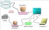

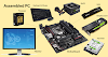


Post a Comment
0 Comments